4. Tsc
The plan parameters include: Phase, Overlap, Pattern, Plan, Date, Channel, Detector, PedDetector, adaptiveParameter, channelLock. The plan can be uploaded and downloaded, and the plan parameter and plan can be copied. Import and export operations.
Click the second parameter icon in the left column of the page to select the parameter configuration that needs to be added or modified.
Enter the parameter configuration page, the upper right corner is the parameter operation bar, which is divided into parameter selection, parameter upload, download, import and export from template, copy parameter, read parameter, you can upload and download the plan, copy the plan parameter and import the plan And export operations.
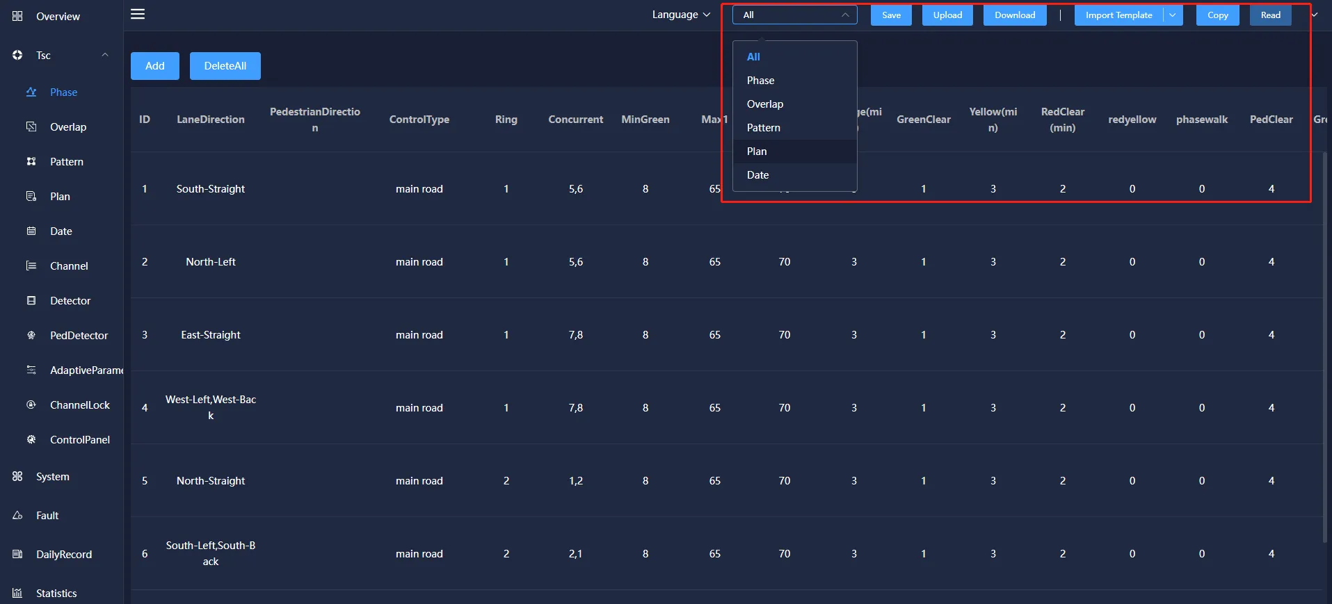
Parameter selection: The specified parameters of the selected equipment can be extracted and viewed. The selection basis mainly includes several selection methods of phase, follow phase, plan, plan, date and all the above parameters.
Parameter upload: below the historical data of the specified parameters of the selected device, click the "upload" button, you can view the current signal timing related parameter data.
Parameter download: Add, modify and delete the corresponding signal timing parameters of the specified device and save and send it to the device, so that the signal timing plan of the current device runs according to the modified data.
Import template : The template import function is divided into two options: file import and file export. Click "File Import" to import external files into the device, so that the device can quickly import the signal timing plan in the file, which is convenient and quick. Click "File Export" to export the signal timing plan of the device into a file mode.
Copy parameters: You can copy the corresponding parameters of the signal timing scheme.
Read parameters: the copied signal timing scheme can be loaded into the device。
4.1 Phase
Phase refers to the signal state of one or more traffic flows that obtain the right of way at the same time within a signal cycle. Usually a signal sequence is composed of red, yellow, and green changes (the pedestrian light group does not have a yellow light).
The phase information mainly includes: phase ID, lane direction, pedestrian direction, control type, ring, concurrent phase, minimum green, maximum green 1, maximum green 2, extended green, green flashing, yellow light, red light clear, red and yellow time, Pedestrian crossing, pedestrian clearing, green pulse countdown, red pulse countdown, vehicle queue threshold, pedestrian waiting threshold, pulse barrier and other information. It can be added, modified, copied and deleted.
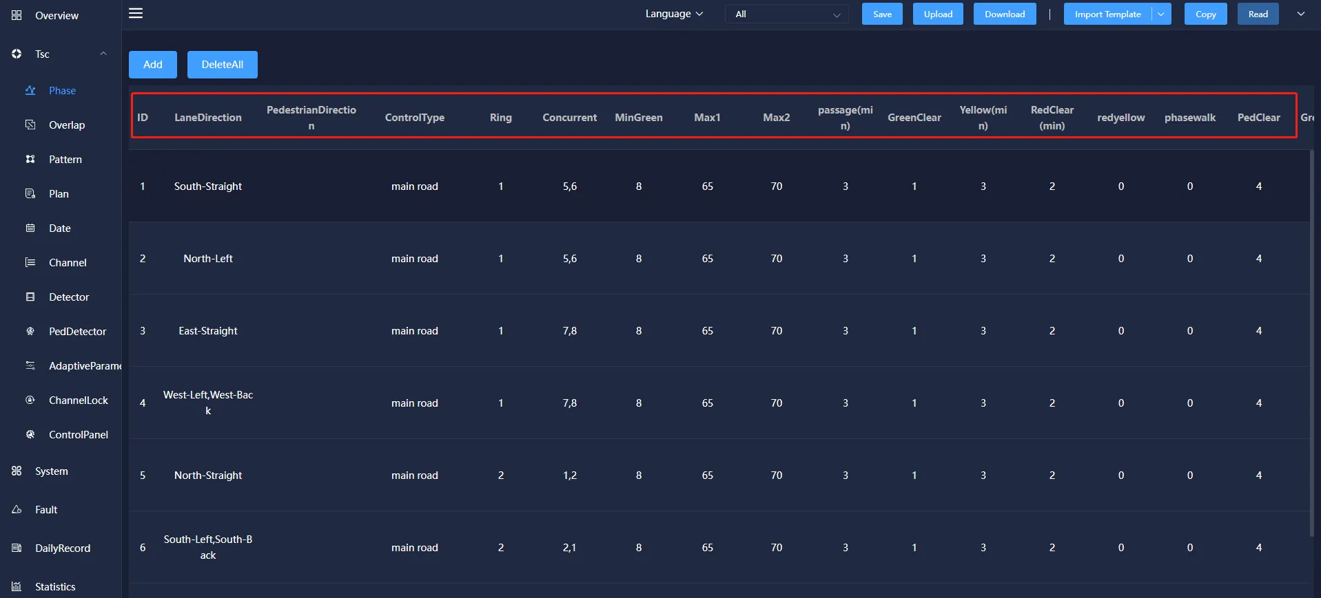
Phase ID: A description of this phase, which is convenient for users to distinguish the phase.
Ring: It is a combination of multiple phases (two or more) release sequences. The phases in the same ring are cyclically released according to the order in which they are arranged in the ring.
Concurrent: The phase allowed to be released at the same time as this bit to judge the conflict phase.
MinGreen: In the induction control mode, the shortest time for the phase to execute the green light.
Max 1: Under the induction control, the longest time that the phase execution green light can be maintained.
Max 2: Under sensor control, when the phase executes the green light to break through the maximum green 1, the maximum green time 2 can be reached.
Passage(min): Under the induction control, the time for each phase to extend the green light.
GreenClear: The flashing time of the green light before the phase execution green light ends and turns to the yellow light.
Yellow(min): the duration for the phase to execute yellow light after the green light ends.
RedClear(min): also known as full red time, which refers to the time for the phase to execute the green light and yellow light before the next phase turns to the green light before the red light is executed.
Redyellow: the phase is executed at the end of the red light and before the green light, the red light and the yellow light are executed at the same time.
phasewalk: green time for pedestrian phase.
PedClear: the flashing time of the green light of the pedestrian phase, the sum of the pedestrian crossing and the pedestrian clearing cannot be greater than the green letter time of the phases.
Greenpulse: when the phase is green, the countdown time displayed in pulse mode.
Redpulse: when the phase is red, the pulse mode countdown shows the time.
Vehicle Queuing Threshold: the critical value of vehicle queue length.
Pedestrian waiting Threshold: the critical value of pedestrian waiting time.
PulseType: You can choose to send pedestrian and motor vehicle pulses, motor vehicle pulses, pedestrian pulses, and turn off pedestrian and motor vehicle pulses in four forms.
The lane direction can be set according to the plan requirements, and one or more lane directions can be selected.
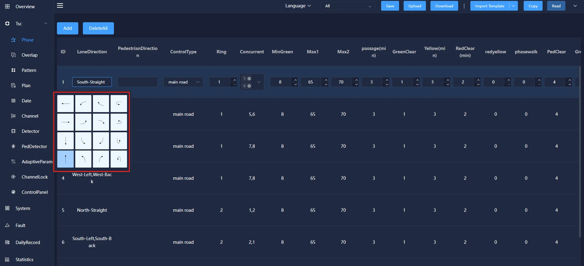
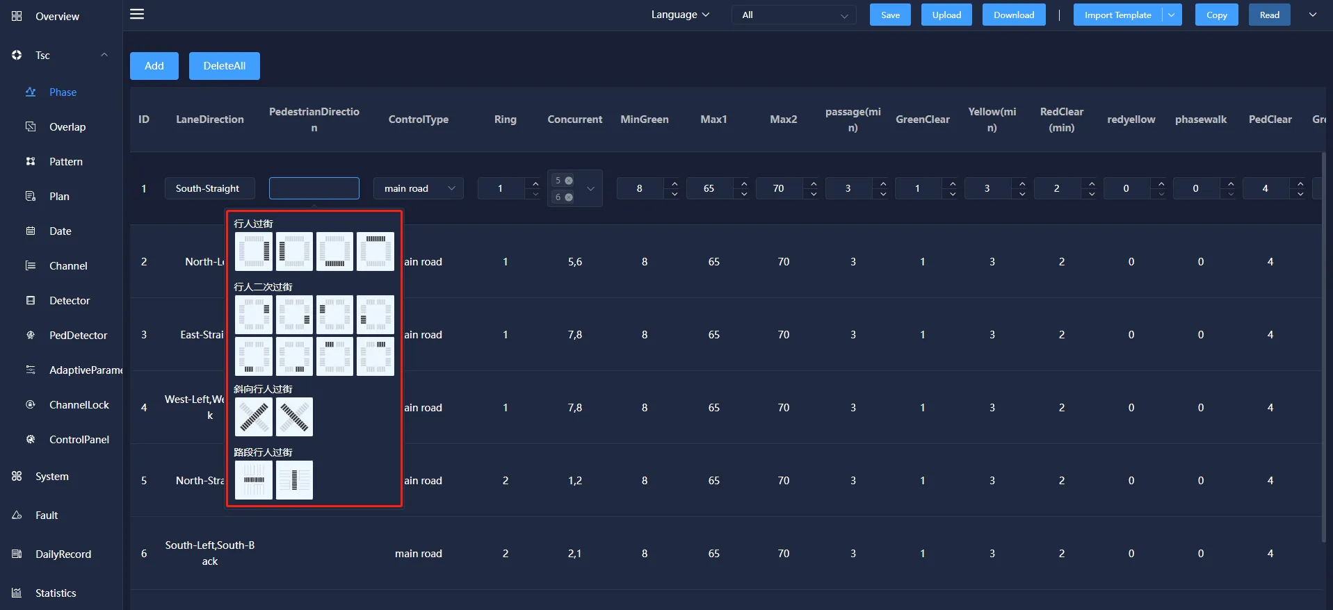
Pedestrian direction can be set according to the requirements of the plan, and four types of pedestrian crossing, pedestrian crossing, oblique pedestrian crossing and pedestrian crossing can be selected.
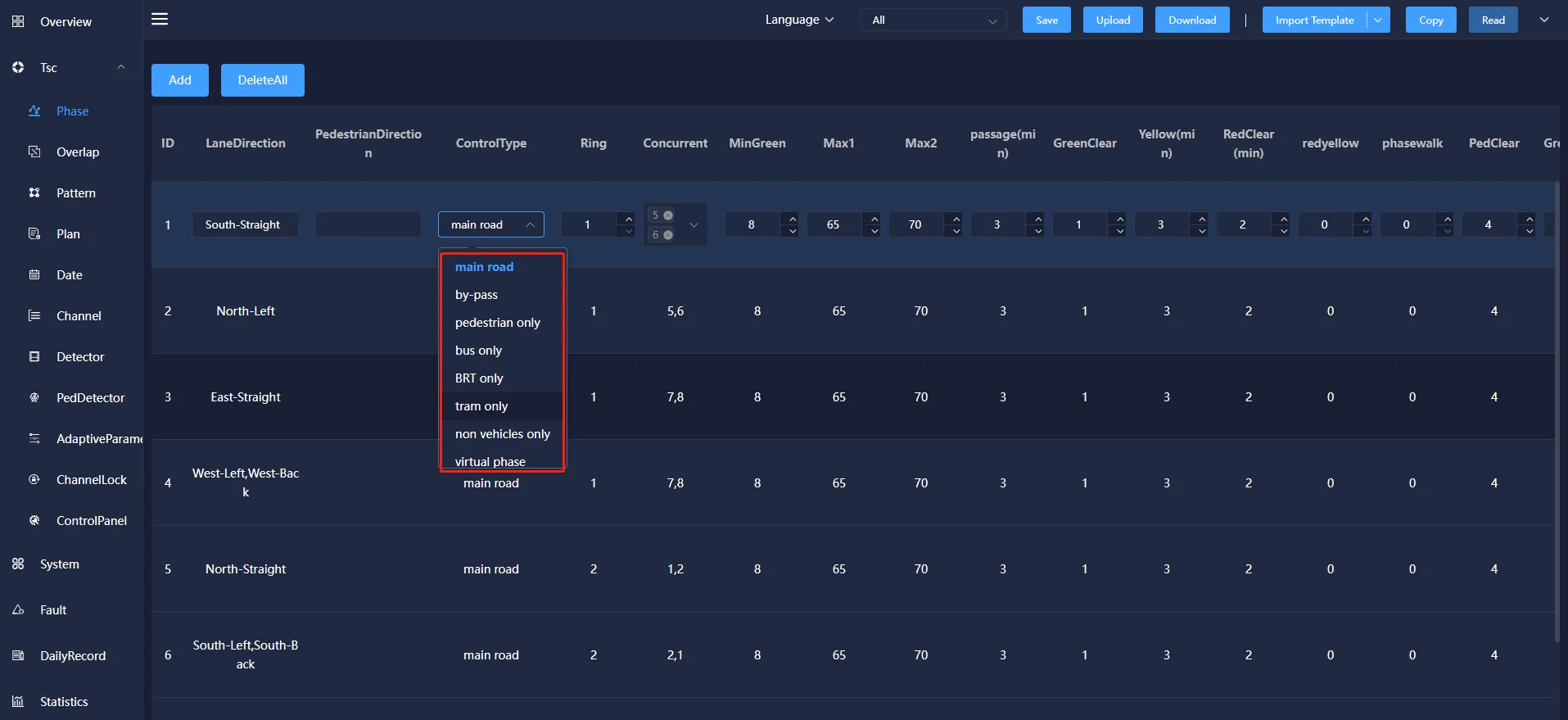
The control type can be selected from main road, by-pass, pedestrian only, bus only, BRT only, tram only.
4.2 Overlap
Overlap is a special traffic signal. It determines the signal output according to the signal state of its parent phase, that is, when the parent phase is released, the follow phase also releases, and the parent phase stops releasing. The following phase also stops releasing.
Overlap mainly includes: phase ID, lane direction, pedestrian direction, description, mother phase, pulse shielding and other information. You can add, modify, copy, and delete information.
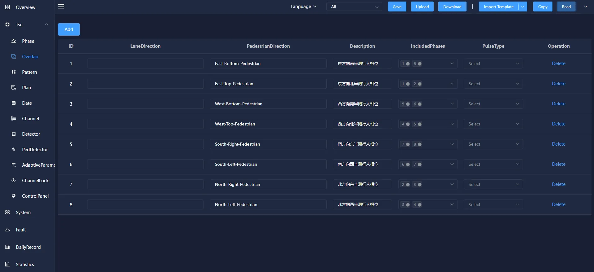
Included Phase: the motor vehicle phase followed by the following phase.
Pulse Type: You can choose to send pedestrian and motor vehicle pulses, motor vehicle pulses, pedestrian pulses and turn off pedestrian and motor vehicle pulses in four forms.
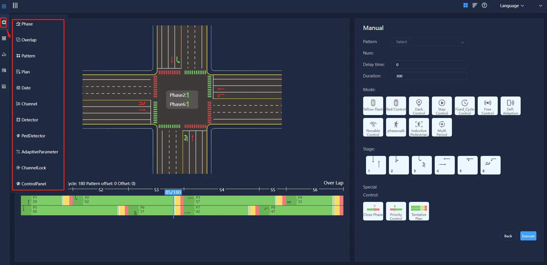
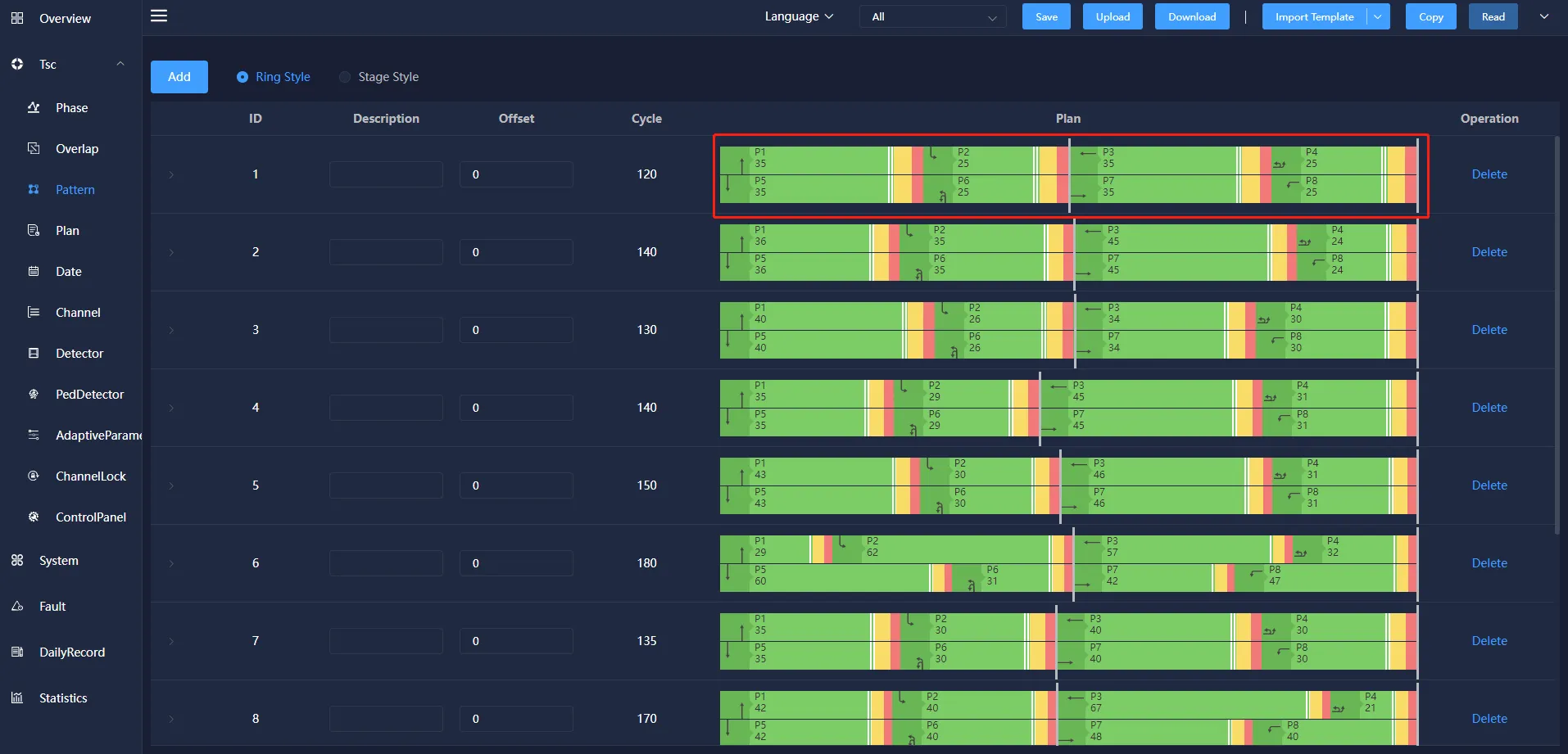
4.3 Patten
The patten is used to configure the intersection by selecting different main phases, and to configure the release time and the release order of each phase.
The patten information mainly includes: ID, description, phase difference, period, phase phase phase-forbidden, phase phase-shielded, phase-coordinated phase phase phase phase phase phase and so on. You can add, modify, and delete them.
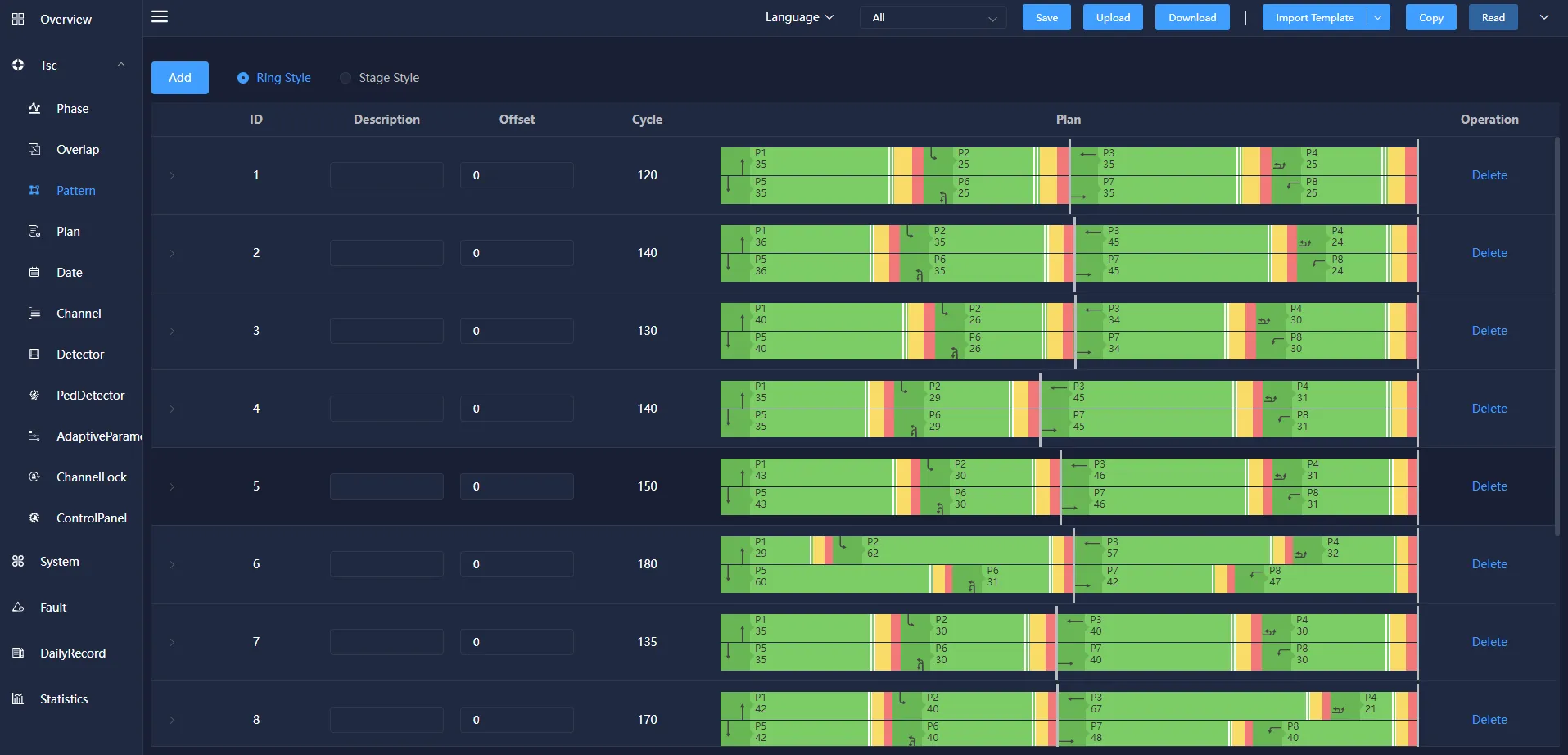
offset: In Wireless Coordinated Control, the difference between the start time and the end time of a designated reference intersection phase.
Cycle: The time required to run all phases. The semaphore displays the time needed for a round according to the set phase sequence, and generates the periodic chart automatically according to the configured main phase green signal ratio time.
4.4 Plan
The plan is used to configure the control mode and control scheme of a natural day Semaphore, and defines the corresponding operation of the semaphore at different time of day. The control mode includes yellow Flash, all red, turn off, fixed cycle control, single point induction control, no cable control, pedestrian crossing control.
The plan information mainly includes: ID, Plan Time, control method and scheme, etc. You can add, modify, and delete them.
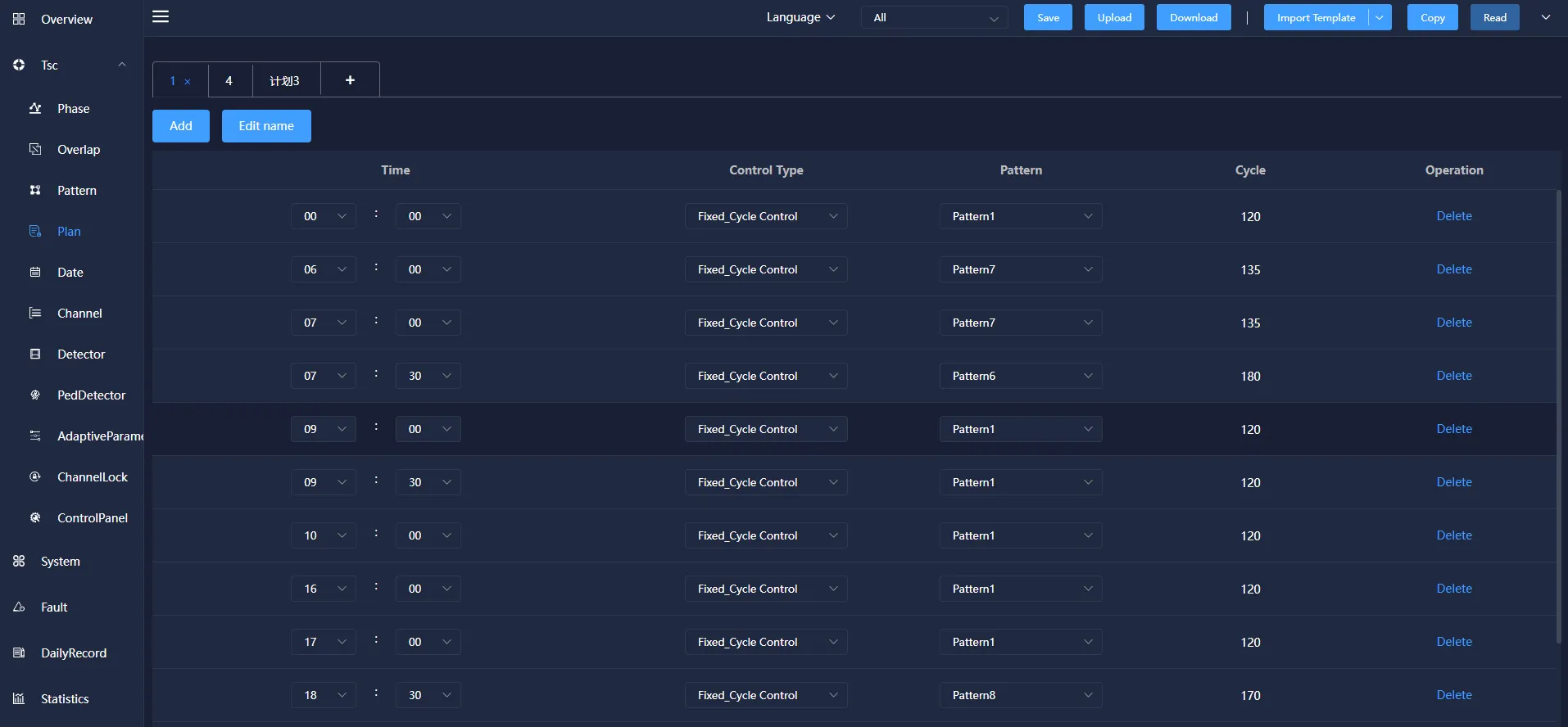
The control methods include: Yellow Clear, Red Control, Dark Control, fixed cycle control, Free Control,Self-adaptive control, Nocable control.
Yellow Clear: All phases of the signal machine change to yellow Clear state.
Red Control: All phases of the signal machine become all red.
Dark Control: the signal machine turns off the output of all phases.
Fixed cycle control: the way that the signal machine implements the signal timing plan to control the flow of traffic.
Self-Adaption : The central control computer collects the traffic flow data of the intersection detector in real time, and generates the corresponding signal timing plan through the timing optimization software, which is a control method for real-time control.
Nocable Control:There is no signal control line connection between the control machines, and the related coordinated control is realized by adopting a common time base synchronization.
The choice of the plan can choose the corresponding plan number according to the design requirements.
4.5 Date
Date refers to the execution of different daily plans on different dates on the signal machine.
Date information mainly includes: ID, description, month, week, date and schedule number. It can be added, modified and deleted.
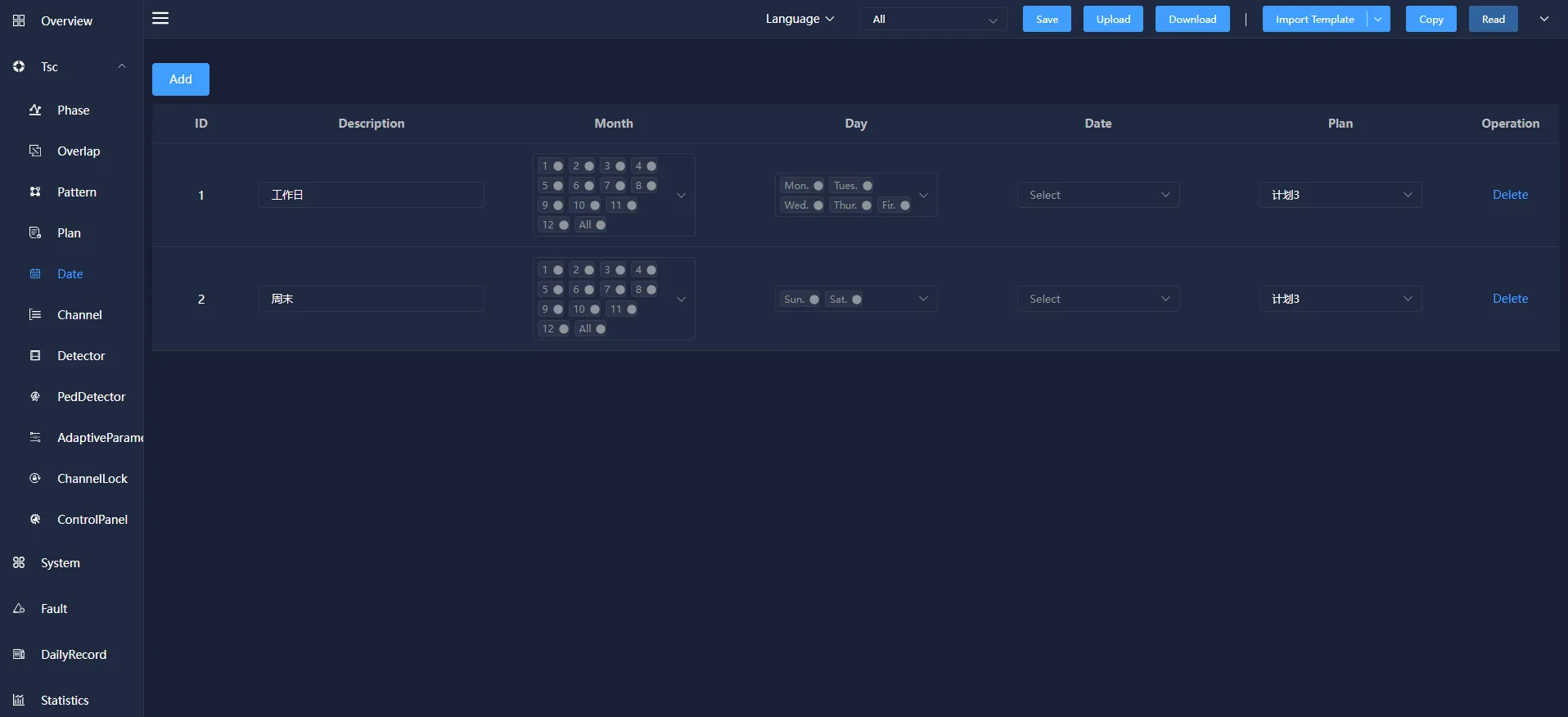
Date information mainly includes: ID, description, month, week, date and schedule number. It can be added, modified and deleted.
Week: Indicates that the corresponding schedule will be executed on the selected day of the week, which is included in all weeks.
Date: Indicates that the corresponding schedule will be executed on the selected date, which is included in all months.
4.6 Channel
Channel configuration is to associate the channel and phase of the signal light group on the light control board.
Channel information mainly includes: ID, Description, control type/source, Connection, Voltthresh, Pacthresh, Peakhthresh, Peaklthresh, etc. It can also be added, modified, copied, and deleted.
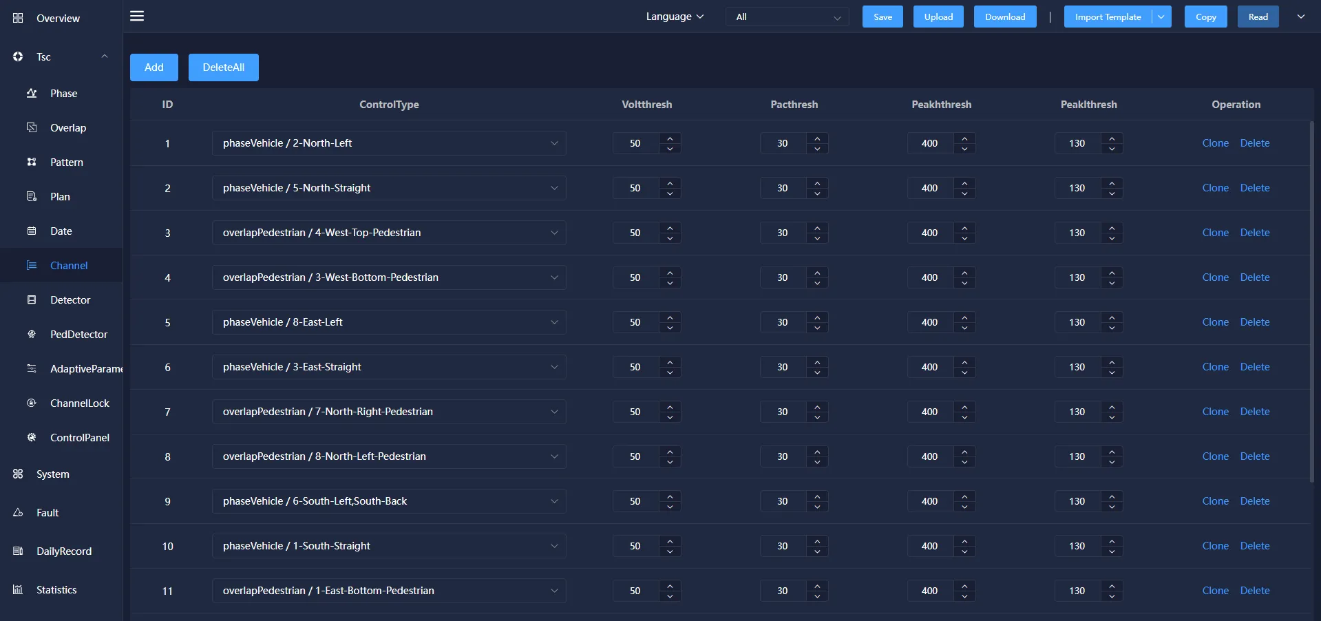
ID:Channel information mainly includes: ID, signal lamp location, control type/source, Connection, Voltthresh, Pacthresh, Peakhthresh, Peaklthresh, etc. It can also be added, modified, copied, and deleted.
Description: According to requirements, the signal lamp position corresponding to each phase can be set.
Control type: The output type selection of the channel control source is divided into motor vehicle phase, pedestrian phase, and follow phase.
Control source: the phase corresponding to the channel light color change.
Connection: A physical line from a node to an adjacent node without any other switching nodes in the middle.
Voltthresh: The Voltthresh the voltage value of the lamp. Generally set to 50v.
Pacthresh: The pacthresh the power value of the lamp. Generally set to 30w.
Peakhthresh: the peakhthresh value judged by the threshold, generally set to 400W.
Peaklthresh: the peaklthresh value judged by the threshold, generally set to 130W.
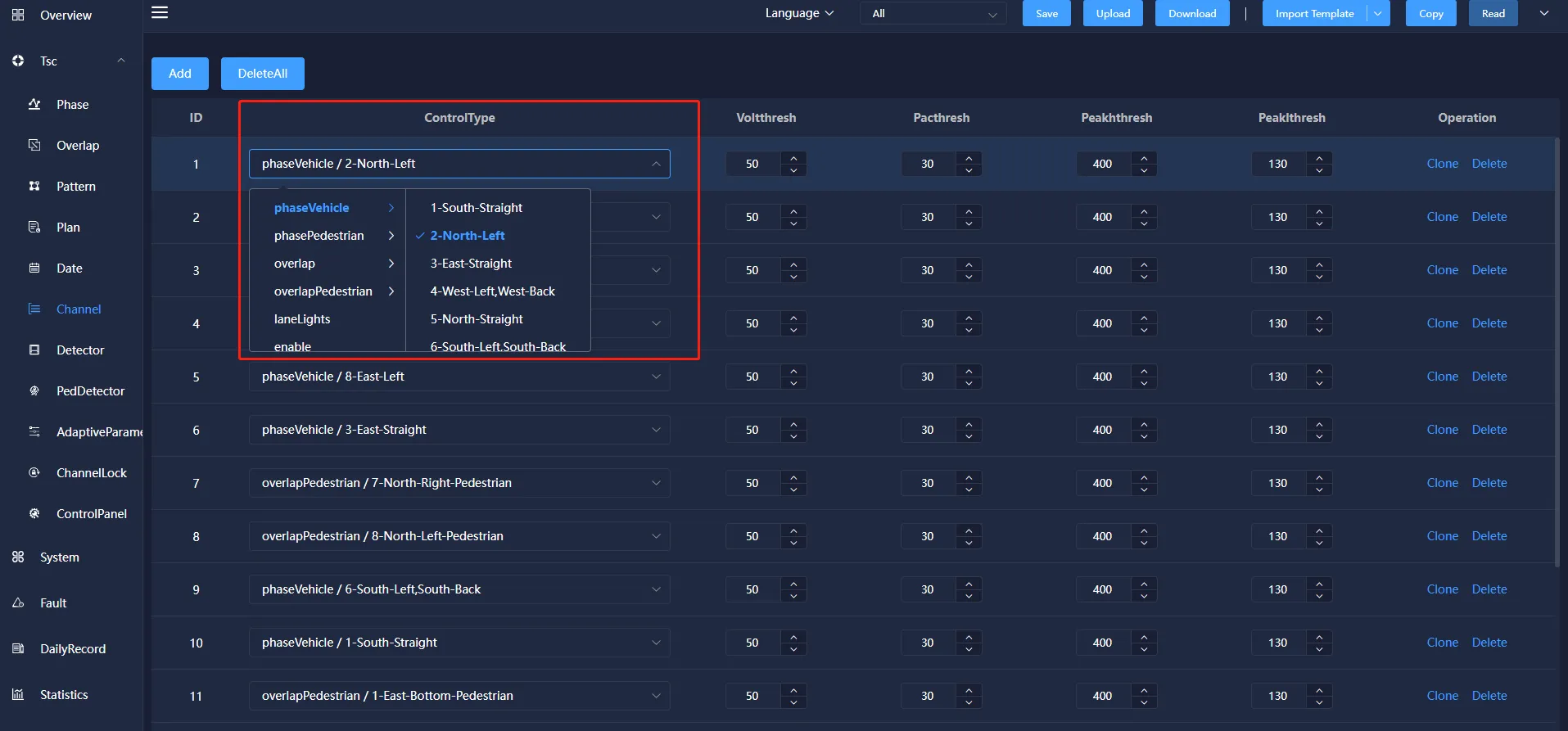
Phase Pedestrian: Pedestrian's right to exercise. Phase Pedestrian generally includes at least two light groups, and can also include multiple light groups.
Overlap: the phase that needs to be coordinated when running in coordination mode.
4.7 Detector
Detector configuration, used to associate front-end traffic detection equipment, configuration of each direction of traffic data and the corresponding relationship between the scheme main phase.
Detector information includes: ID, Description, Type, Request phase, No Activity, MaxPresence, Erratic counts,Fail Time, enable, mode, existence time, sensitivity, sampling time, threshold, departure threshold, departure filter, departure filter and saturation flow. You can also add, modify, copy, and delete them.
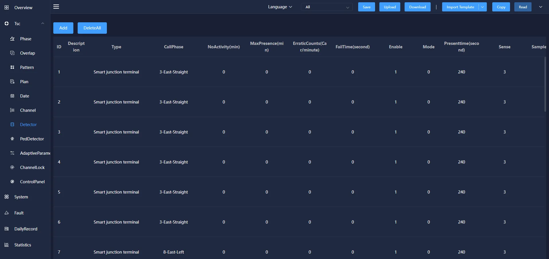
Callphase: The vehicle detector corresponding to the motor vehicle phase, when the detector detected a signal through the vehicle, the corresponding request phase will respond.
No Activity(min): The detector does not detect the passing of the vehicle during this time, which means that the detector is out of order and the function is not enabled when the value is zero. Unit: minutes.
MaxPresence(min): The detector has been detected during this period of time through the vehicle, indicating that the detector failure. When the value is zero, the function is not enabled. Unit: minutes.
Erratic counts(car/minute): Detector Uncertainty Count Diagnostic parameter. If an active detector is over-responsive, the diagnostic device is considered to be faulty and the detector is considered to be failed. Setting this object value to zero turns off the diagnostic for the detector, in seconds per minute.
Fail Time(second): The request for the detector is cancelled if there is no record during the failure time before the request is answered. The detector type can be either coil or smart junction terminal.
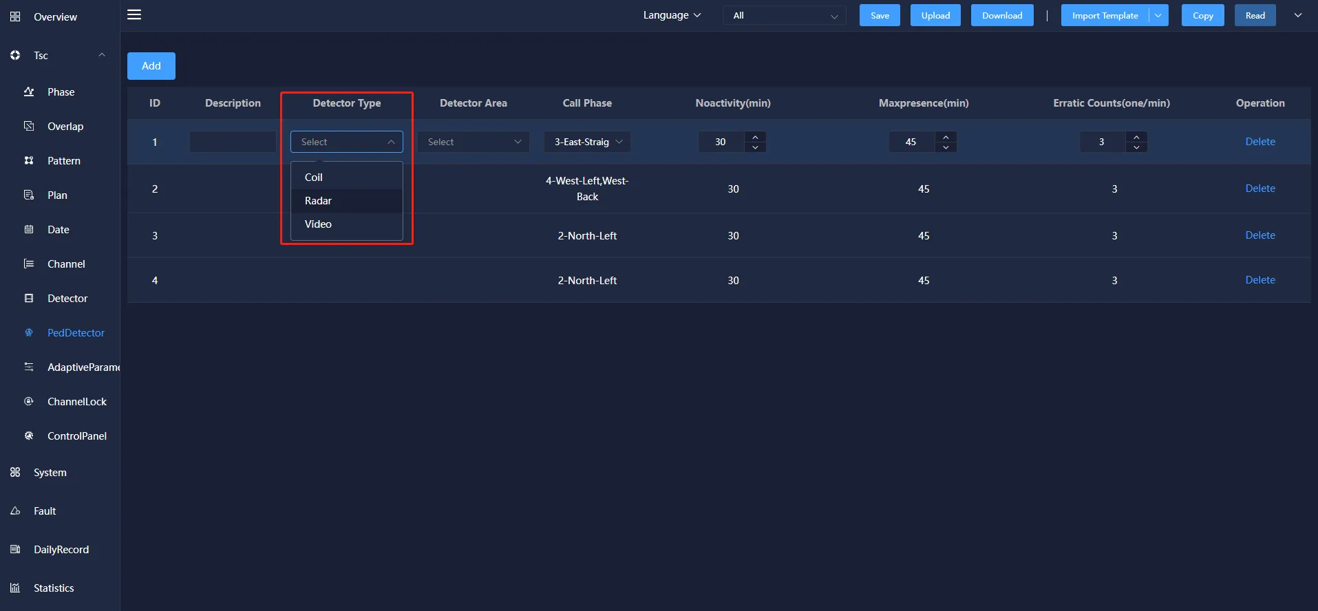
4.8 PedDetector
Pedestrian detector is to detect the presence of pedestrians in the detection area or through the situation.
Pedestrian detector information mainly includes: ID, description, detector type, detector area, request source, no response time, maximum duration, maximum number of requests, etc.
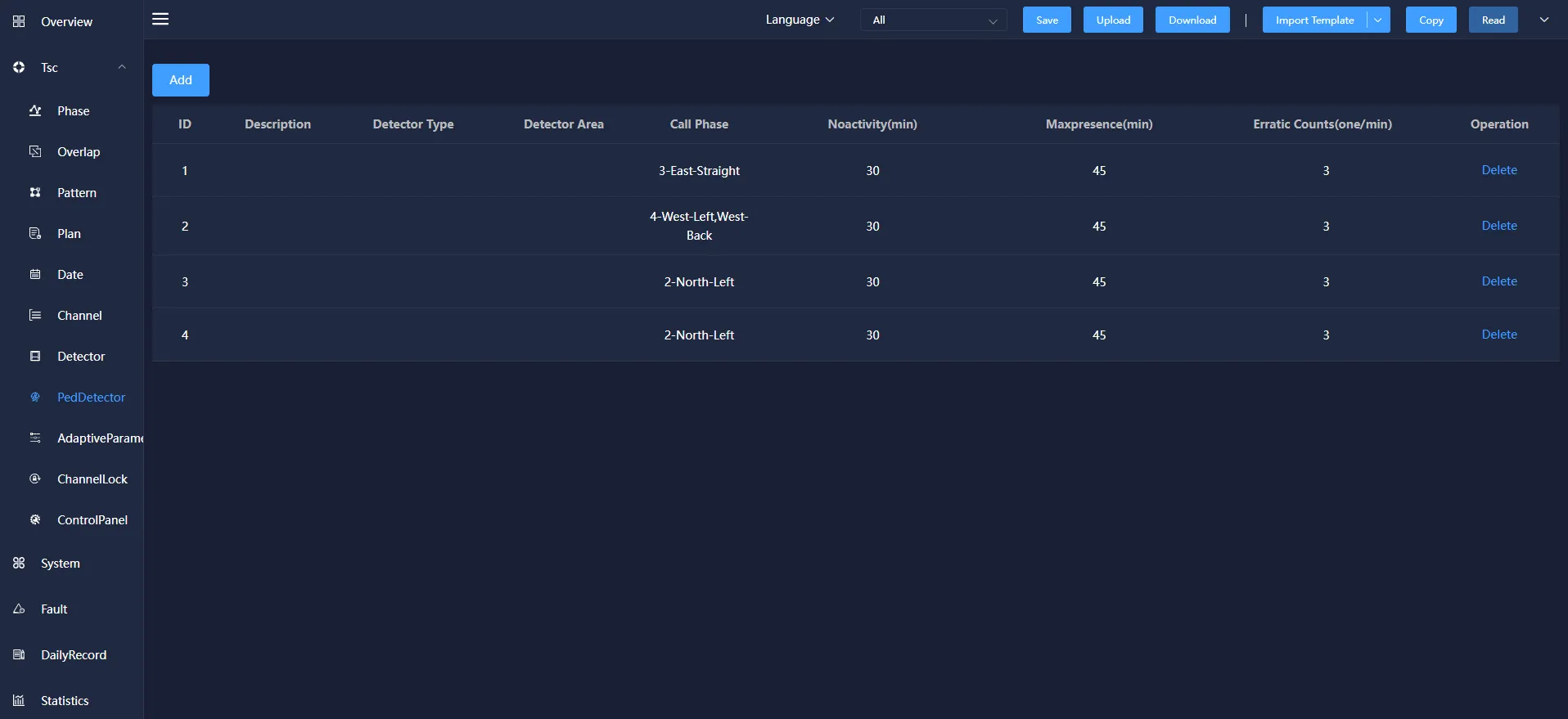
Call phase: the motor vehicle phase corresponding to the pedestrian detector. When the detector detects the signal of vehicle passing, the corresponding request phase will respond.
Noactivity:The detector does not detect a vehicle passing within that period of time, indicating that the detector is malfunctioning and that the function is not enabled when the value is zero. Unit: minutes.
Maxpresence: The detector has been detecting the passage of vehicles within this period of time, indicating that the detector has failed. When the value is zero, the function is not enabled. Unit: minutes.
Erratic Counts: The detector does not determine the number of diagnostic parameters. If an activity detector is too sensitive, the diagnostic equipment considers it to be faulty and the detector is considered to be a failure. If the value of this object is set to zero, the diagnosis of the detector will be turned off, unit: times/minute.
Failure time: Before the request of the detector is responded, if there is no record within the failure time, the recording request will be cancelled.
There are three types of detectors: coil, radar and video.
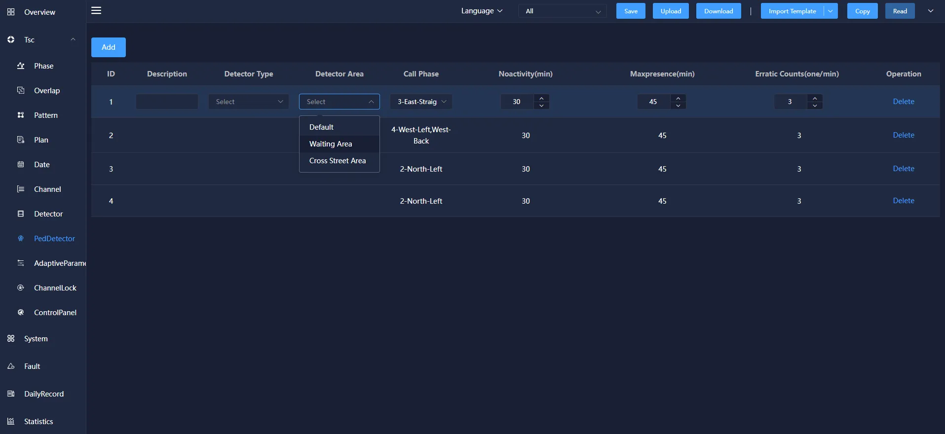
The detector area has three types: default, waiting area and cross street area.
4.9 Adaptive Parameters
Adaptive parameters refer to setting the corresponding parameters in the plan according to the operating plan.
The adaptive parameter information mainly includes: Pattern, LossTime of the Green Beginning, LossTime of the Yellow Ending, Saturation Flow,Self Learning Mode, static weight, cycle adjustment factor and other operations. It can be added, modified and deleted.
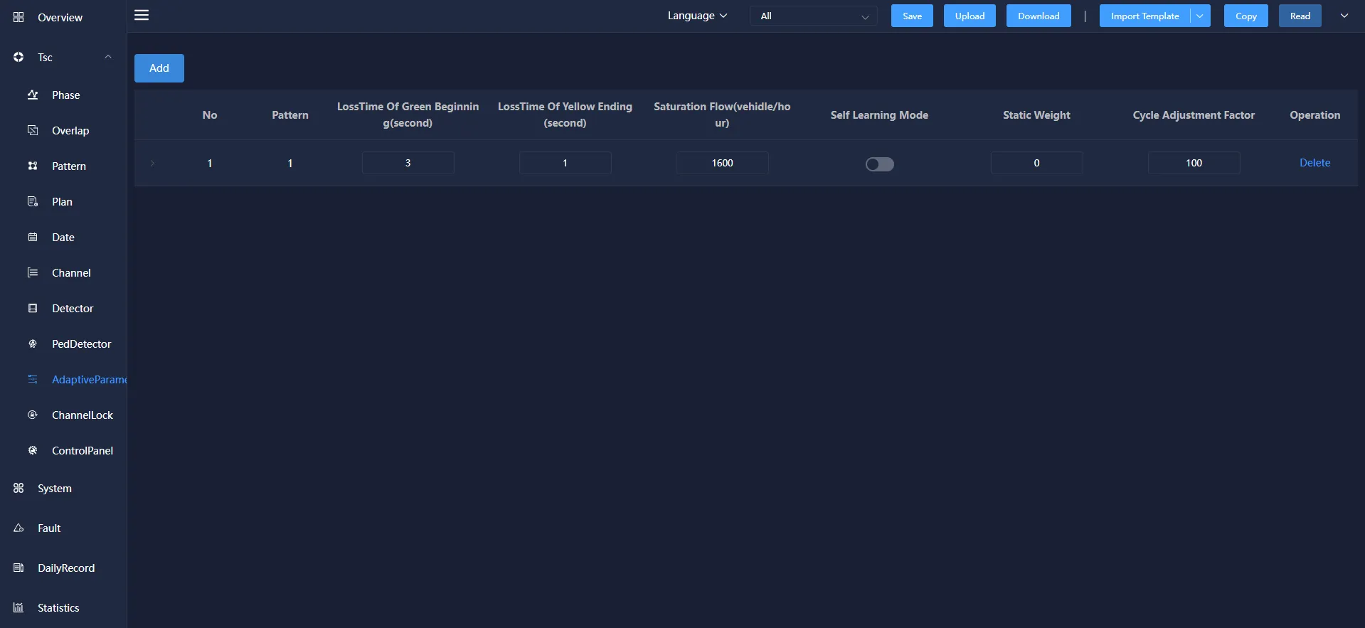
Pattern: The scheme refers to the scheme used by selecting different main phases to configure the intersection.
LossTime of the Green Beginning: At the beginning of the green light, it is difficult for the traffic flow to enter at a saturated flow rate. Therefore, the lost transit time is called the loss time at the beginning of the green period.
LossTime of the Yellow Ending: At the end of the end of the yellow light, the traffic flow that crosses the stop line has an unsaturated flow rate, so the lost transit time is called the yellow end loss time.
Self Learning Mode: the maximum flow of vehicles passing through the parking line at an intersection in a unit time, that is, the steady flow of vehicles passing through the parking line in a unit time when the queued vehicles accelerate to the normal speed, in pcu/h.
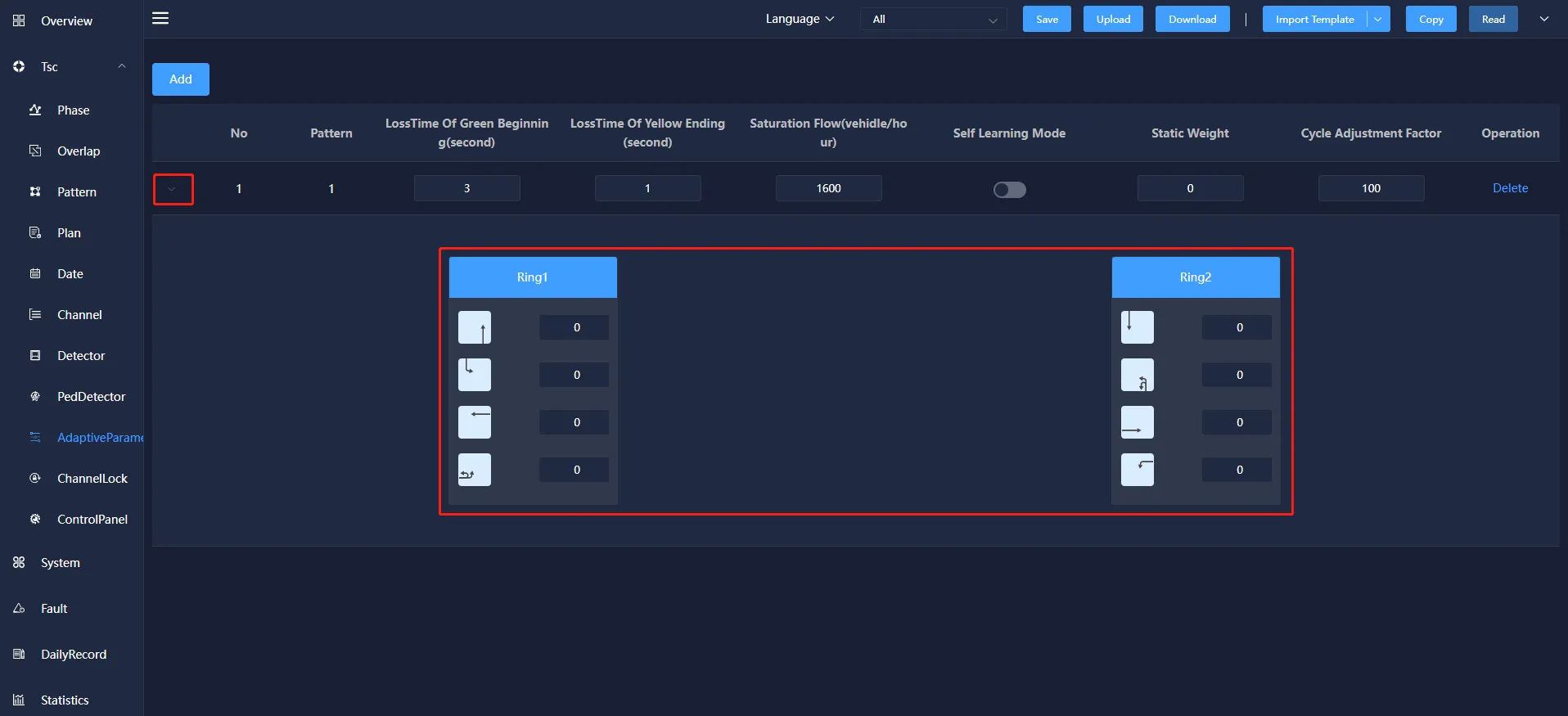
Click the ">" button to view and modify the ring information of the current scheme.
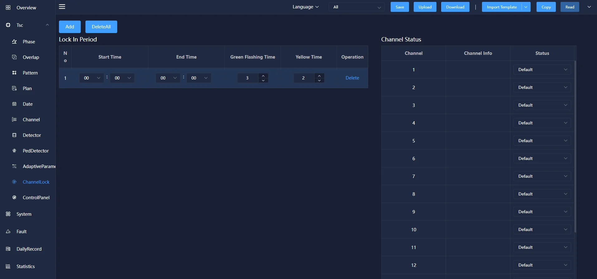
4.10 Channel lock
Channel lock means that the set channel is locked in the corresponding time period.
Channel lock information mainly includes: start time, end time, green flashing time, yellow time and other operations. It can be added, modified and deleted.
Start time:The time when the channel lock is turned on.
End time:Turn off the channel lock time.
Green flashing time:A period of time before the green light turns to yellow light, the green light flashes, prompting the motor vehicle signal light to switch to yellow light.
Yellow time:Some time before the yellow light turns to red, the yellow light flashes, prompting the motor vehicle signal light to switch to red light.
Channel status:channel, channel information and status. The status information bar includes: default, red light, yellow light, green light, green flashing, off light and red flashing status. The corresponding channel status can be selected according to the channel information.
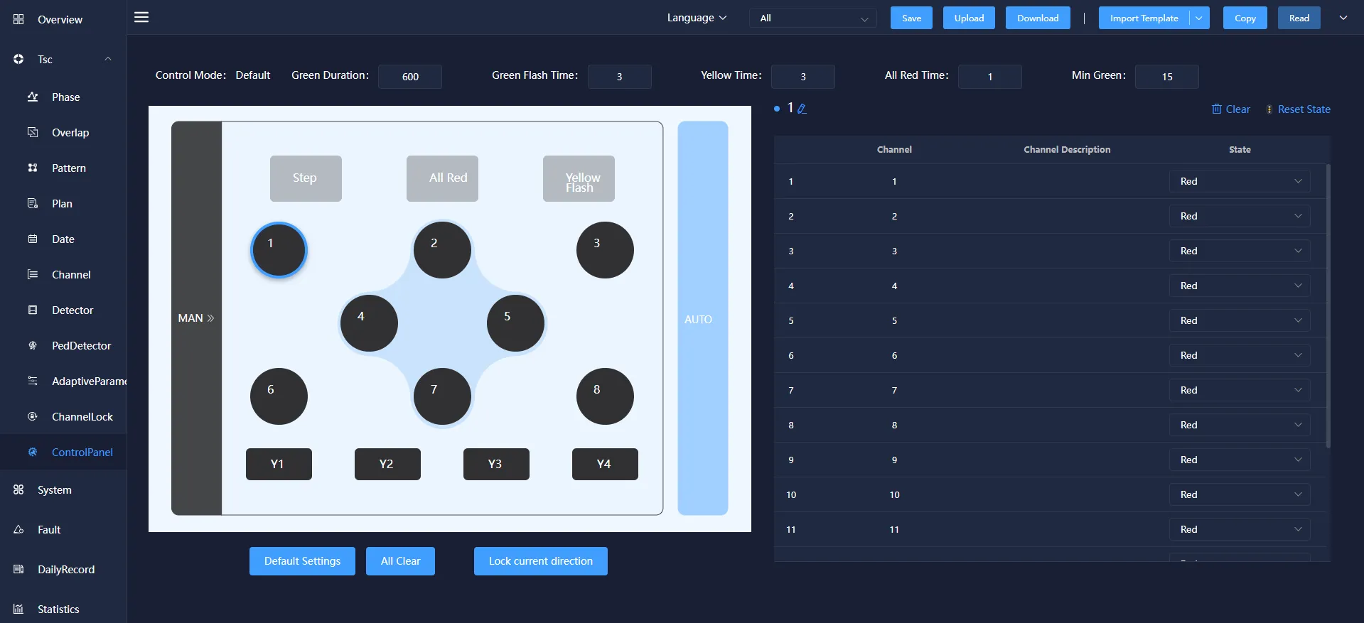
4.11 Channel Panel
Channel panel means that the signal phase parameter configuration of the signal machine can be manually adjusted in this interface.
In the channel panel, you can configure parameters such as "Duration", "Green flashing time", "Yellow time", "All red time" during manual control. You can also select the buttons in the figure, configure the corresponding relationship between each button and channel, and issue the device to take effect.