5. system
The system can view information, remote control, channel detection, real-time channel and device information and other configuration functions.
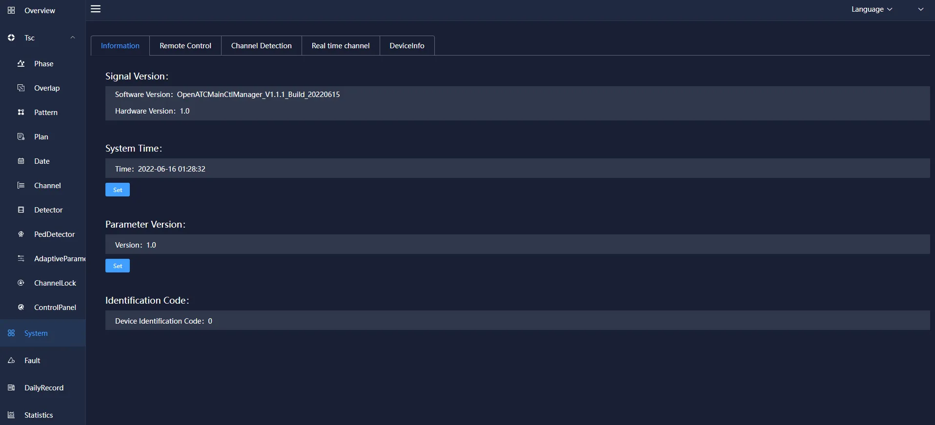
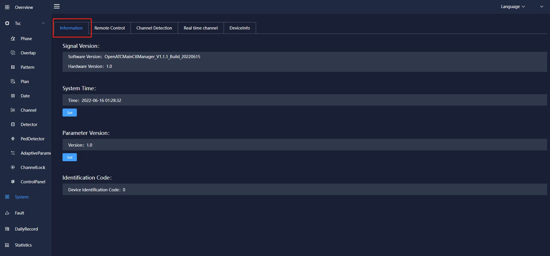
5.1 information
It mainly includes: the management and viewing of information such as signal machine version, current system time, characteristic parameter version, identification code (equipment identification code) and remote debugging.
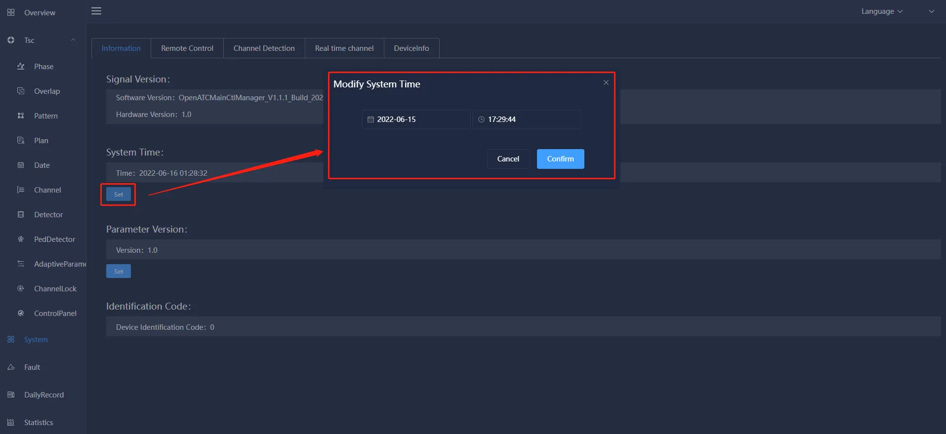
Click the setting under the current system time, a pop-up box for modifying system time will pop up, you can set the current system time, click OK, and the time will be updated to the latest set time.
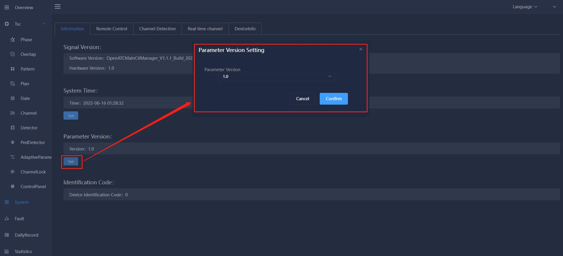
Click the setting under the feature parameter version, the feature parameter version setting pop-up box will pop up, you can set the version number of the current feature parameter version, and click to confirm the version number to update to the latest version number.
5.2 remote control
Mainly include: remote control operation (restart, authorization, custom) settings, system update and data update operations.
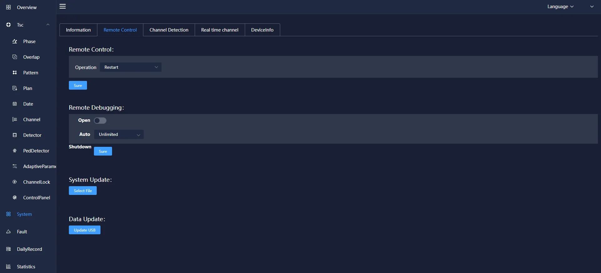
Choose to enable remote debugging, you can choose the time to start (unlimited, 5 minutes, 60 minutes), select the corresponding configuration and click confirm to prompt that the setting is successful.
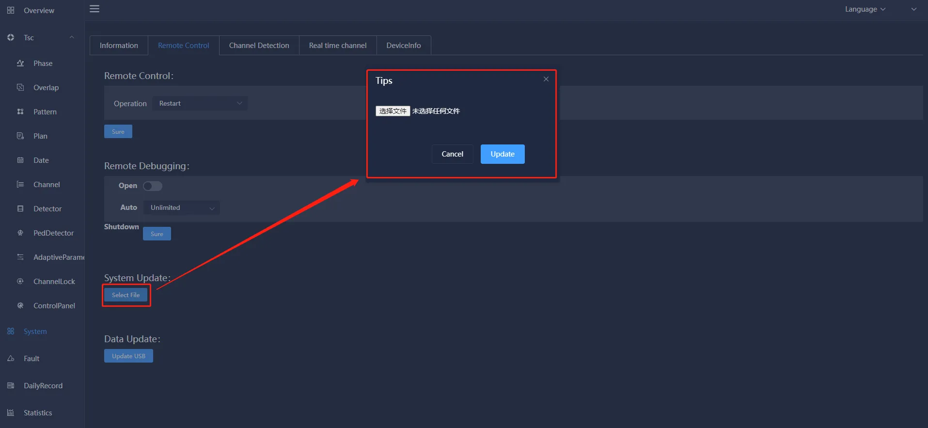
Click Select File under System Update, a pop-up box for selecting a file will pop up, select the file to be uploaded, and click Update.
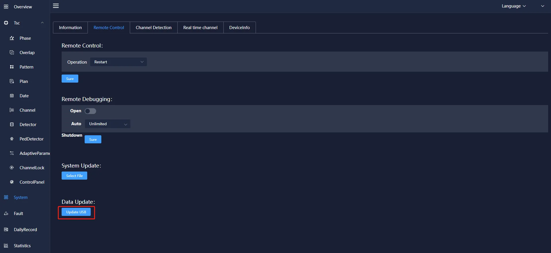
Click Update U Disk Data under Data Update to prompt that the update is successful.
5.3 Channel detection
Click to select the display lamp on the light control board, click the "Detect" button, and the channel information will be displayed, mainly including: channel, channel input voltage, red light residual voltage, red light output voltage, red light off residual power, red light on Information about the output power of the lamp, the residual voltage of the yellow lamp, and the output voltage of the yellow lamp. Click the "Restore" button to restore it.
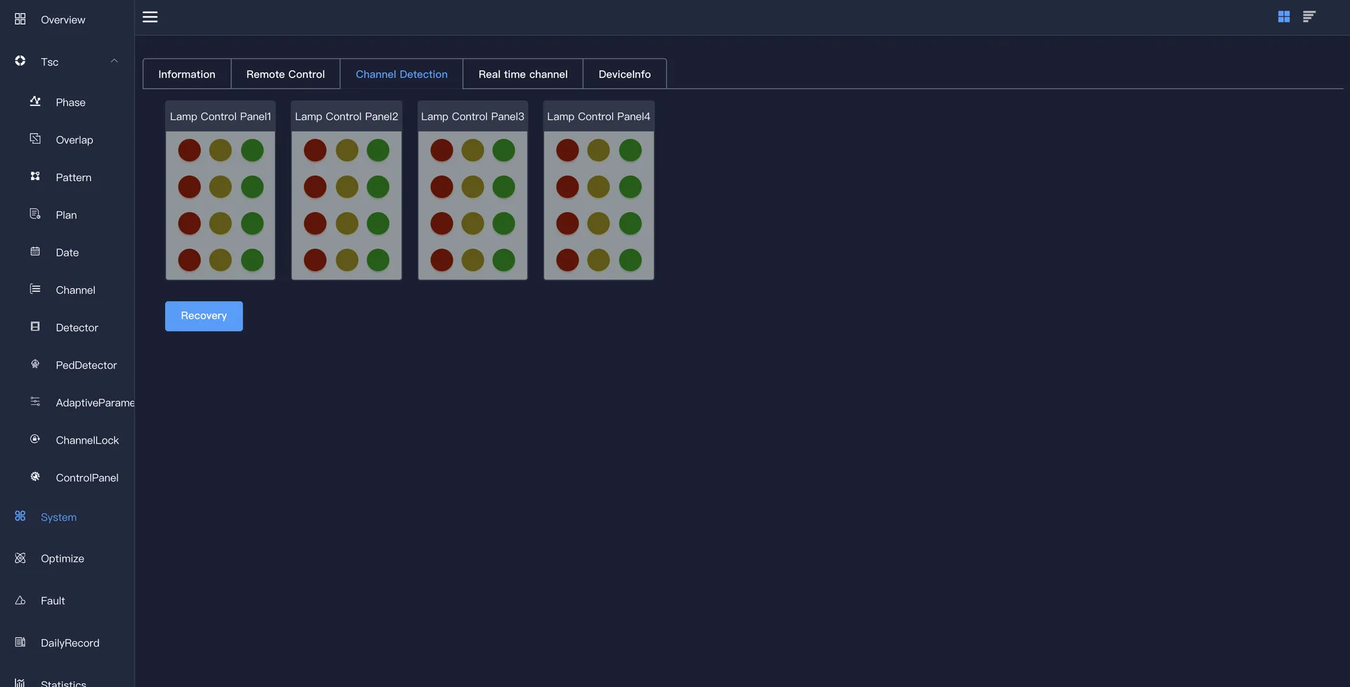
Click Restore to restore the original state of the light control version and prompt the successful restoration.
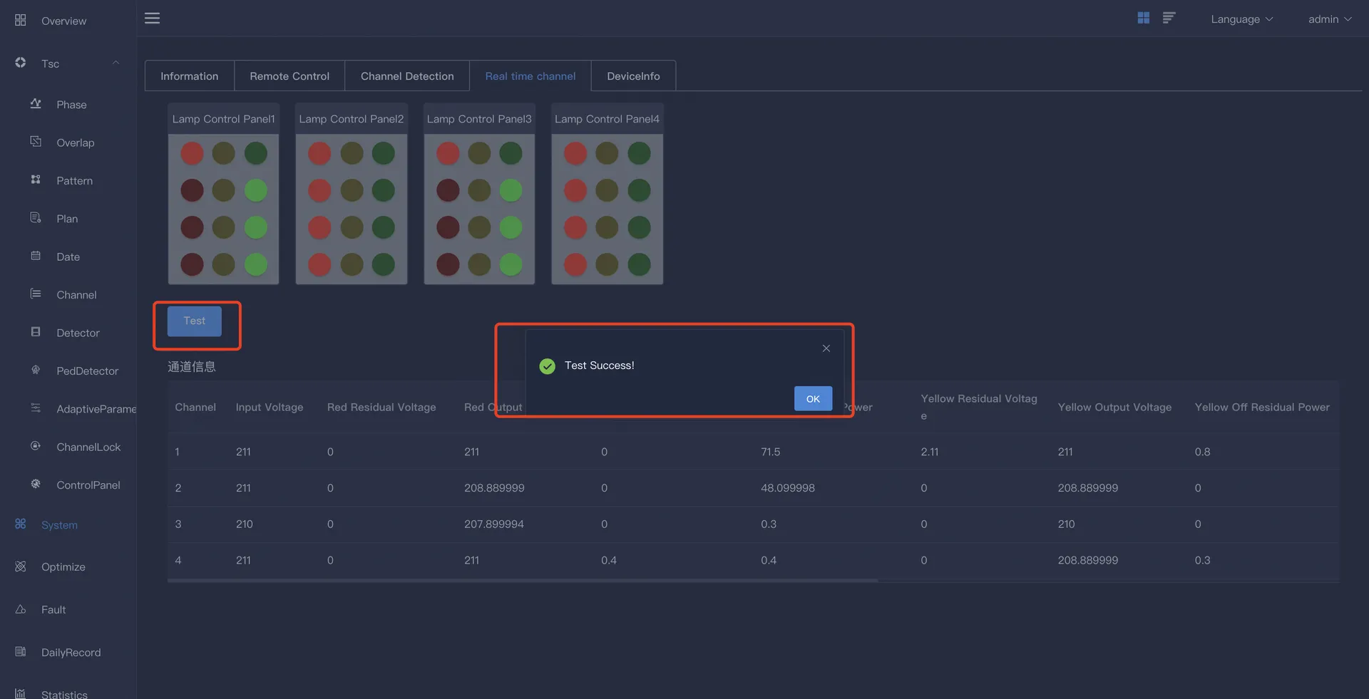
5.4 Real-time channel
Display the status of the lights implemented by each channel in the configuration plan, which is related to the phase.
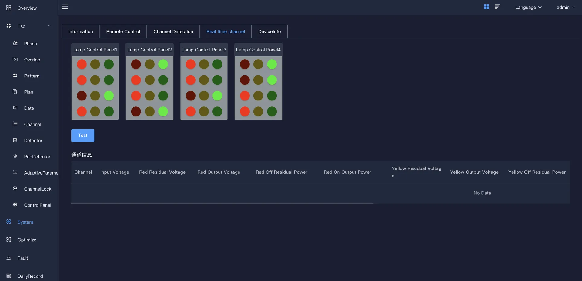
Click the "Detect" button, the channel information will be displayed, and a pop-up box will prompt that the detection is successful.
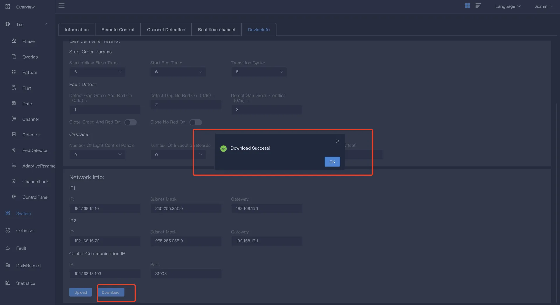
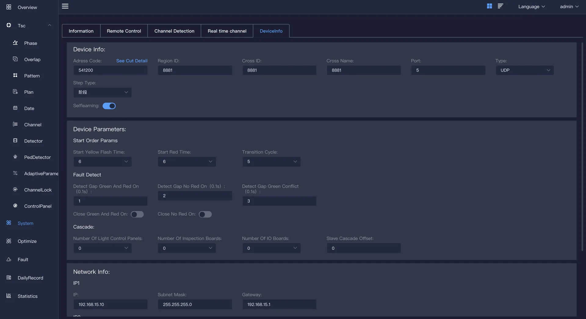
5.5 Device Information
Mainly include: equipment parameters and network card and other information. It can be modified and other operations, after the modification is completed, the "upload" or "download" operation can be performed.
Equipment information includes: address code, area ID, intersection ID, intersection name, port, type (TCP UDP), step type (stage, color cloth)
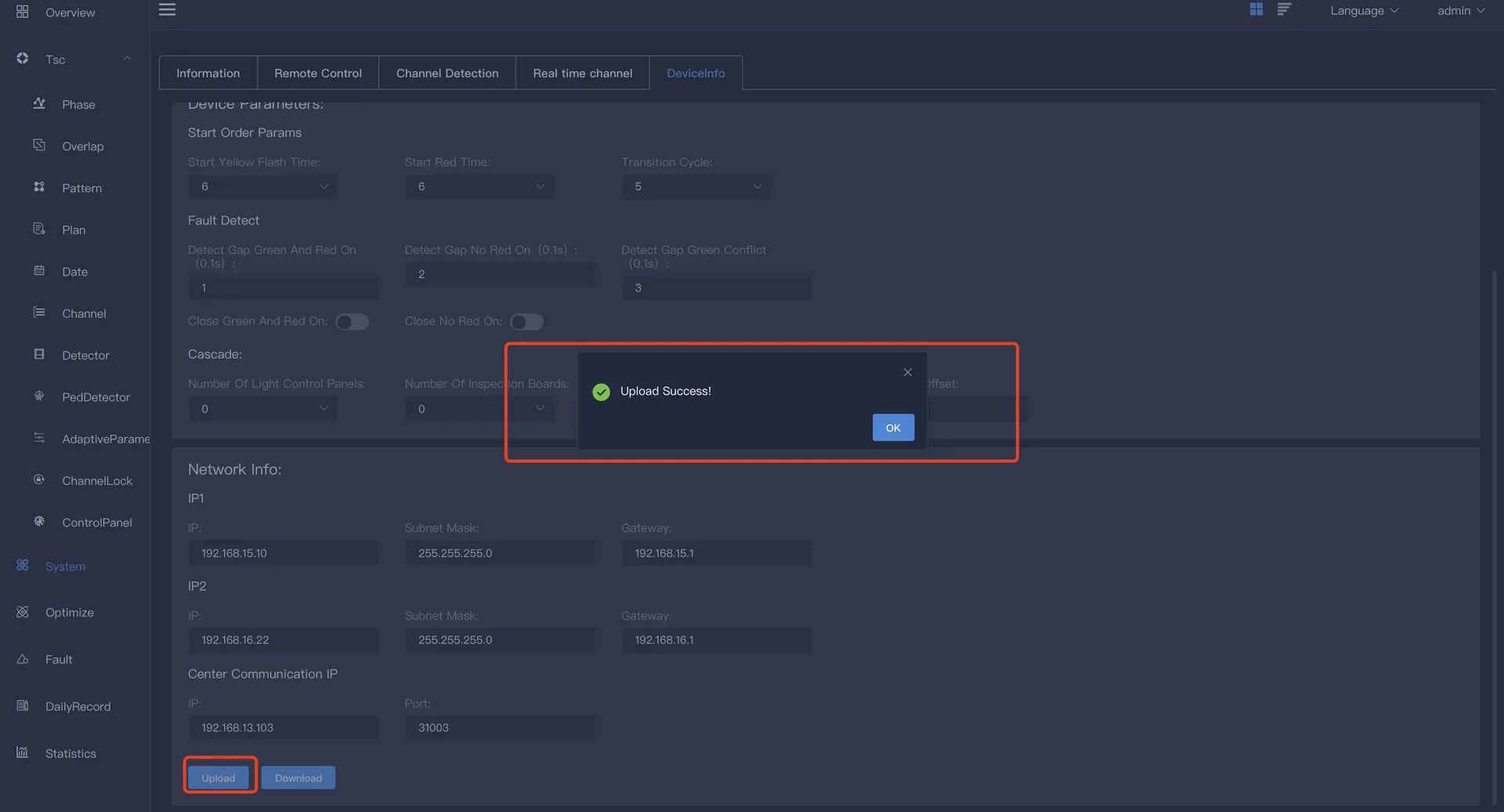
Equipment parameters include: startup sequence parameters, fault detection parameters and cascade. The start sequence parameters include: start yellow flash time, start full red time and green wave transition period. The fault detection parameters include: red and green simultaneous detection time interval, no red light detection time interval, and green light conflict detection time interval. You can click the "red and green simultaneous detection" button and the "no red light detection" button. The cascade includes information such as the number of master light control boards, the number of master vehicle inspection boards, the number of master IO boards, and the offset of slave cascading.
Network card information includes: IP1, IP2 and central communication IP. IP1 is the local IP information, including: IP, subnet mask and default gateway. IP2 is the alternate IP, which also includes: IP, subnet mask and default gateway. The central communication IP includes: IP and port.
Click upload (transmit the signal operation control plan from the lower computer to the upper computer), and the parameter upload success dialog box will pop up. At this time, the device information, network information, device parameters and other information of this device will be uploaded to this page.
Click to download (transmit the signal operation control plan from the upper computer to the lower computer), and the parameter issuance successful dialog box will pop up.