3. GIS
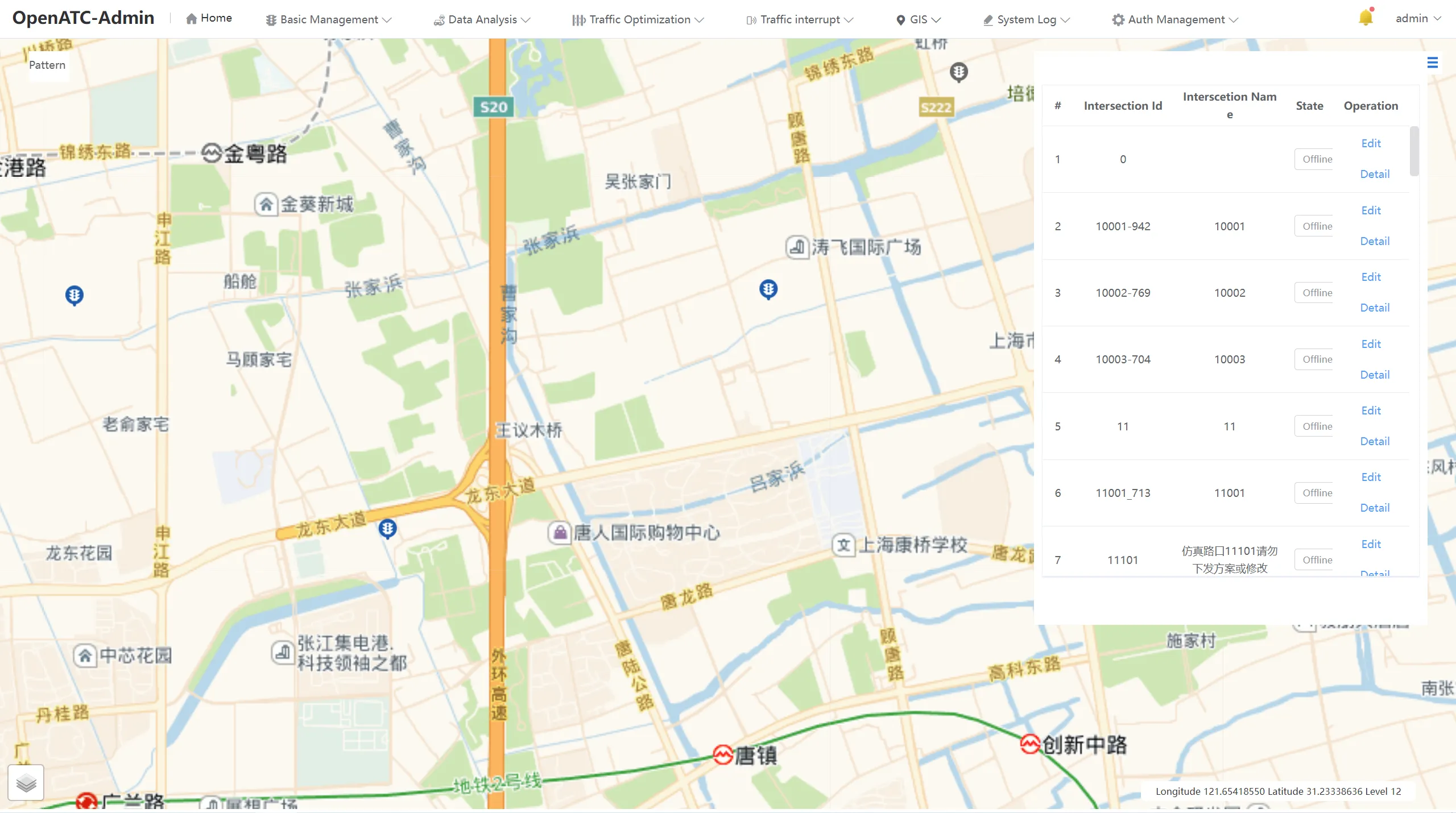
Click the menu bar "GIS" to enter the map interface, where you can view the Device Status, Duty Route and Coordinate Route in the.
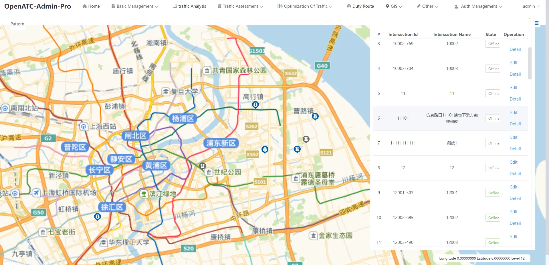
3.1 Equipment Status
The marked points on the map indicate the location of the current device. The blue icon indicates that the current device is online, and the gray icon indicates that the current device is offline.
The ID, names, status, and operations of all intersections are displayed in the display list on the right.
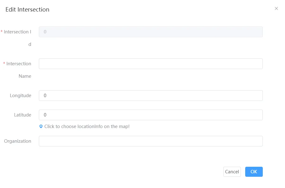
Click to enter the "Edit" interface, set the ID and name of the intersection, and select the coordinate position of the intersection on the map.
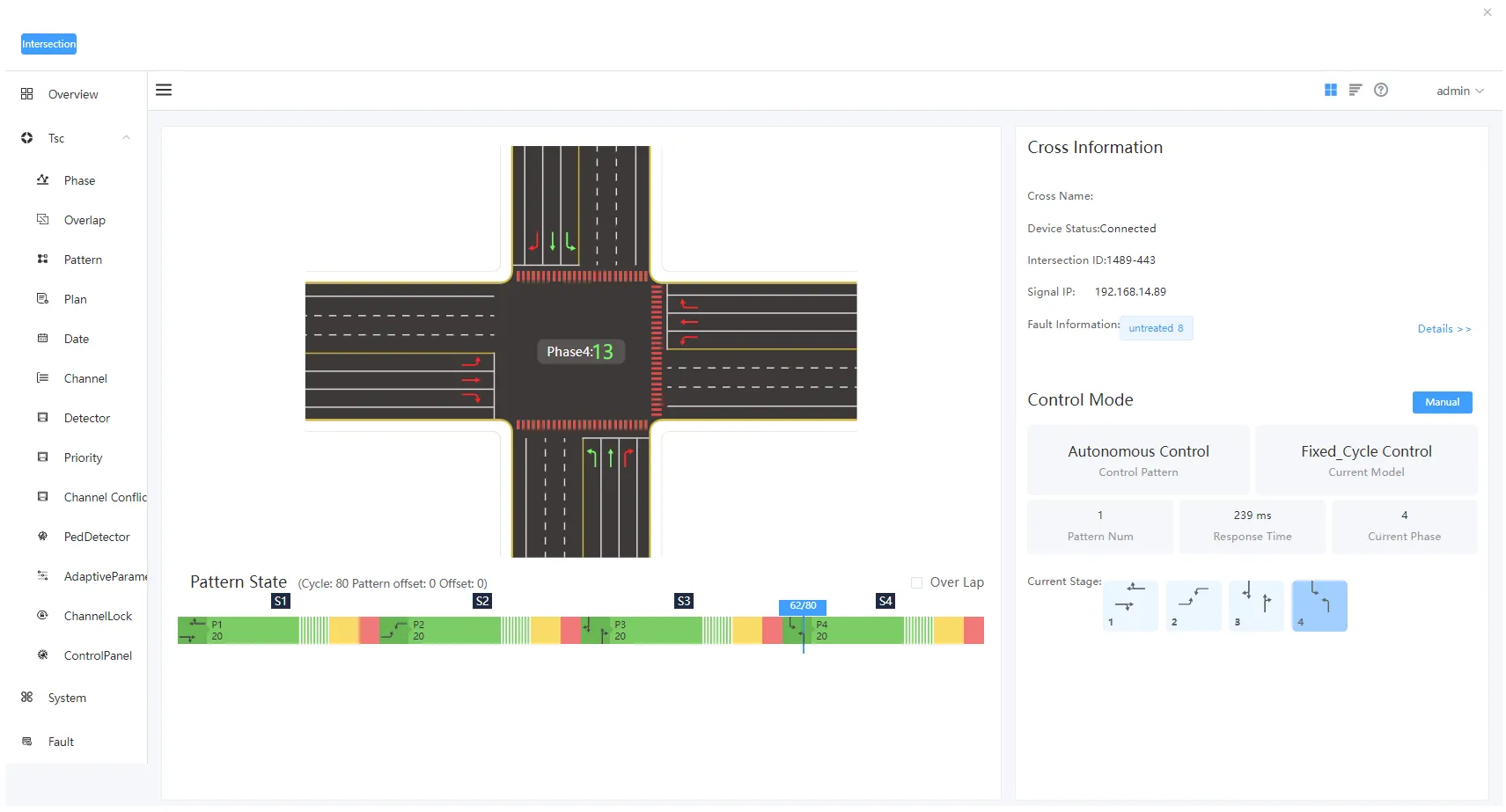
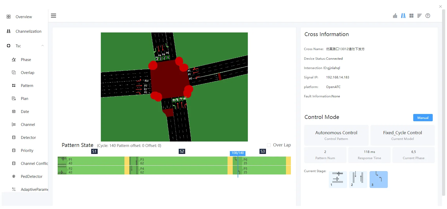
Click "Details" to enter the details interface of the intersection, which displays the real-time signal distribution status of the current intersection. The toolbar on the right side mainly displays the name, device status, signal ID and signal IP of the intersection where the device is located, as well as the control mode of the current device. Control mode, control mode, scheme name, control number, current phase, and request time of the current device.You can check "Follow Phase" in the upper right corner of the View Scheme Status section.
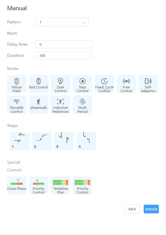
You can select manual control for the control mode. Click manual control to view the delay time, duration, and control mode and phase (resident) of the current device.
Click the "Manual Control" button, you can see the yellow flashing, all red, turn off the lights, stepping, fixed cycle, induction control, adaptive control, no electric coordination, pedestrian crossing, induction pedestrian crossing and Autonomous control mode.
You can select the corresponding control method to control the equipment according to the needs and for each stage.
The details interface has three styles, including: channelization mode, template pattern and text interface.
The template module is shown in Figure 3-3 above, showing the channelization of standard intersections, in which the number of lanes of each entrance road is a fixed number, if you need to view the channelization information of the actual intersection, you need to click "channelization" in the left menu bar to configure channelization.
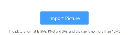
(1) Import Images
First, import the actual intersection image in svg, png, and jpg format, and the image size cannot exceed 10MB.
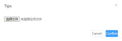
Select the corresponding local image file.
After the image is successfully added, you can enter the channelized information configuration interface, and you can choose to re-import the image in the upper left corner of the interface.
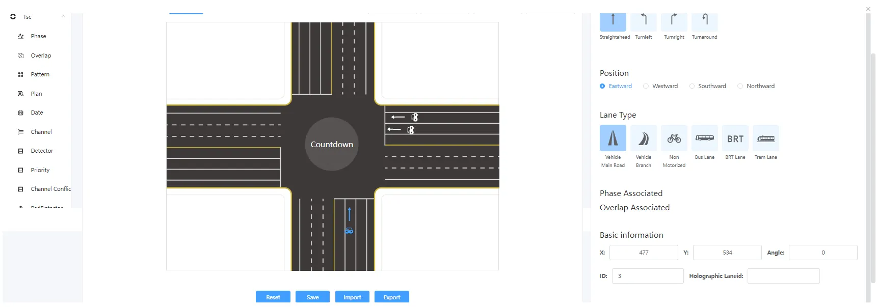
(2)Add Motorways
According to the actual intersection situation, add motor lanes in each entrance direction. Select the "Motor Lane" option above, left-click on a specific lane to complete the addition, you need to select the lane steering, orientation and lane type of the lane, modify basic information such as coordinates and rotation angle, and drag the motorway icon. At the same time, you can view the designation of the motorway, and you can select "Delete" or "Clone" to copy the lane configuration.
Lane Steering: go straight, turn left, turn right and turn around, and the steering can be selected in multiple ways.
Directions: East, West, South, and North.
Lane Type: main road, motor vehicle bypass road, non-motorized road, bus lane, BRT lane and tram, with optional flip display.
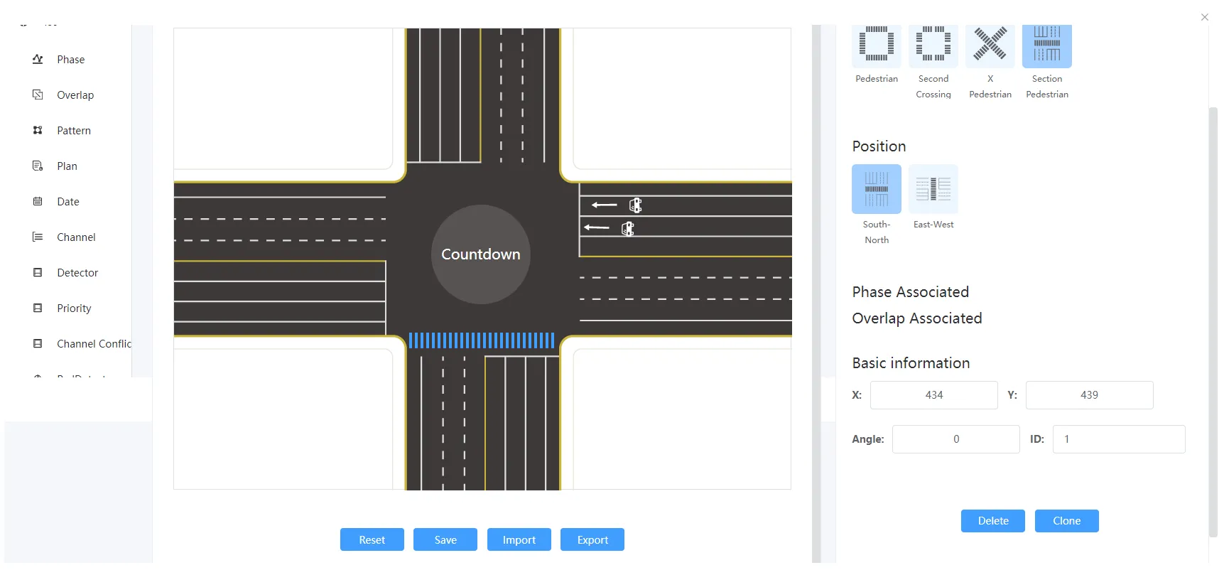
(3) Add ped crossings
According to the actual intersection, add ped crossings in all directions. Select the "ped crossings" option above, left-click in the specific position to complete the addition, you need to select the pedestrian type and orientation of the crosswalk, you can modify the basic information such as coordinates and rotation angle, and drag the ped crossings icon. At the same time, you can view the label of the ped crossings, and you can select Delete or Clone to copy the ped crossings configuration.
Pedestrian types: pedestrian, secondary crossings, pedestrians and section pedestrians.
Positions:
1) Directions under pedestrian, including: east, west, south and north.
2) The orientation under the secondary crossing, including: east-top, east-buttom, west-top, west-buttom, south-left, south-right, north-left, and north-right.
3) Orientation under the X pedestrian, including: X-/ and X-.
4) Directions under section pedestrians, including: north-south and east-west.
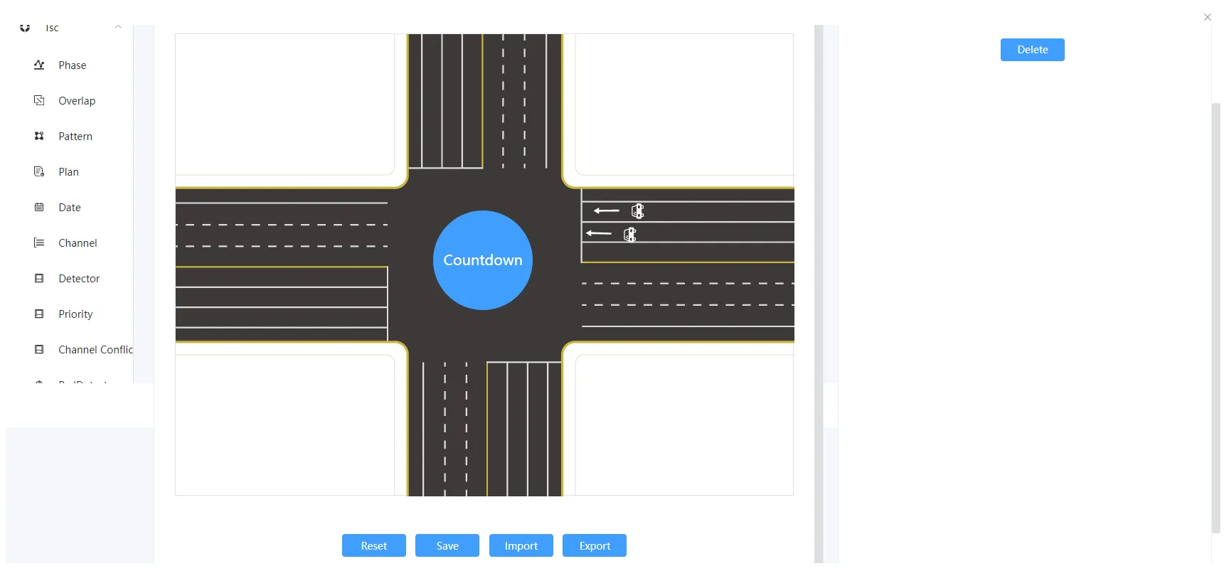
(4) Add a countdown
Select the "Countdown" option above, left-click in the specific position to complete the addition, you can drag the countdown icon. You can optionally delete the countdown.
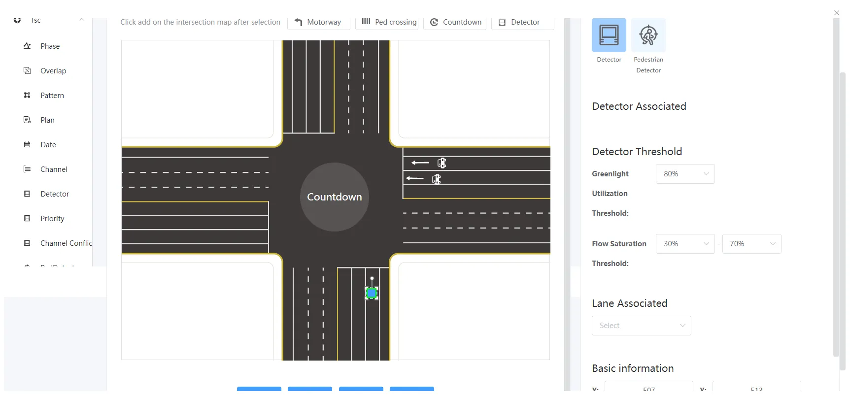
(5) Add detectors
According to the actual intersection situation, add detectors on each lane. Select the "Detector" option above, left-click in the specific location to complete the addition, you need to select the type, threshold and associated lane of the detector, modify basic information such as coordinates and rotation angle, and drag the detector icon. At the same time, you can view the label of the crosswalk, and you can select "Delete" or "Clone" to copy the detector configuration.
Detector threshold: Green light utilization threshold and flow saturation threshold range.
Lane association: Associate the motor vehicle lane ID tag added above.
After configuration, you can click the "Save" button below. You can select Reset to reconfigure.
Click the "Import from File" button and select a local JSON configuration file to directly import the relevant configuration. Click the "Export from File" button to export the JSON format configuration file to the local computer, and then directly import it to the channelization configuration of other intersections.
Click the Replace button in the upper right corner of the overview screen , which can be directly replaced by the actual channelization interface of the intersection, which can view channelization configuration information, including motorways, pedestrian crossings, countdowns, and detectors, as shown in the following figure:
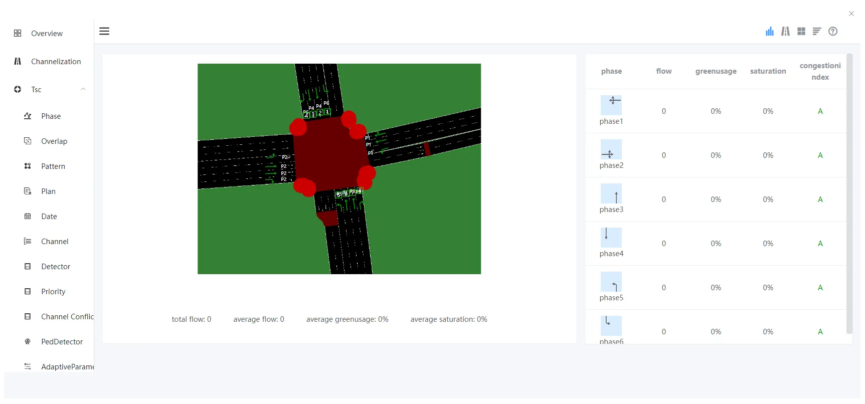
Click the Replace button in the upper right corner of the overview screen , you can view the traffic statistics of the intersection, including: total traffic, average flow, average green light utilization, average traffic saturation, corresponding traffic in all directions, green light utilization, saturation and congestion index, as shown in the following figure:
Click the interface replacement button in the lower right corner , Can be directly replaced with a simple style interface based on text, as shown in the figure below:
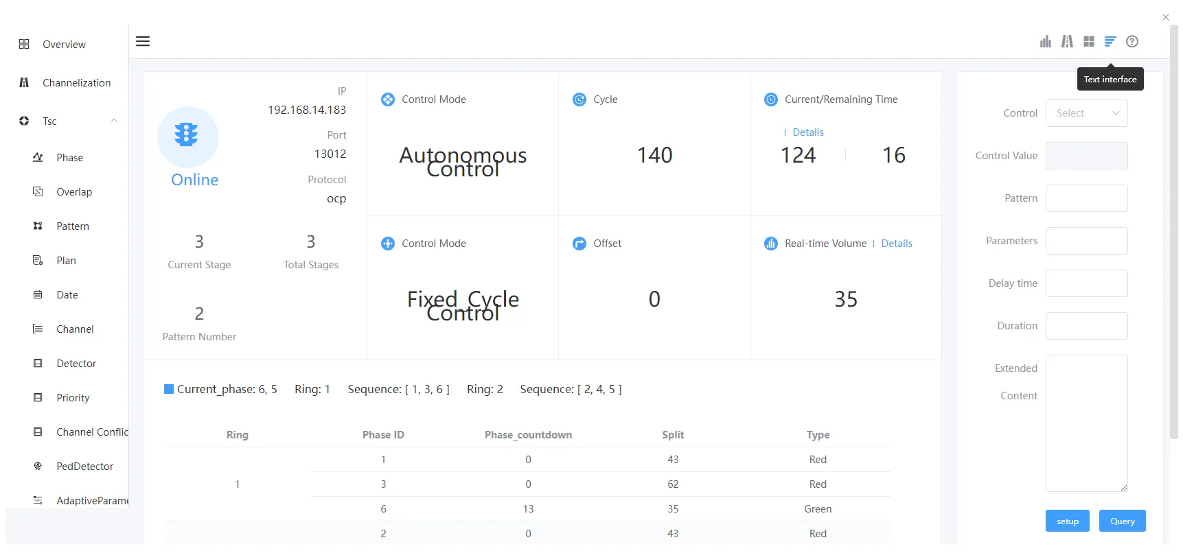
Toolbar:
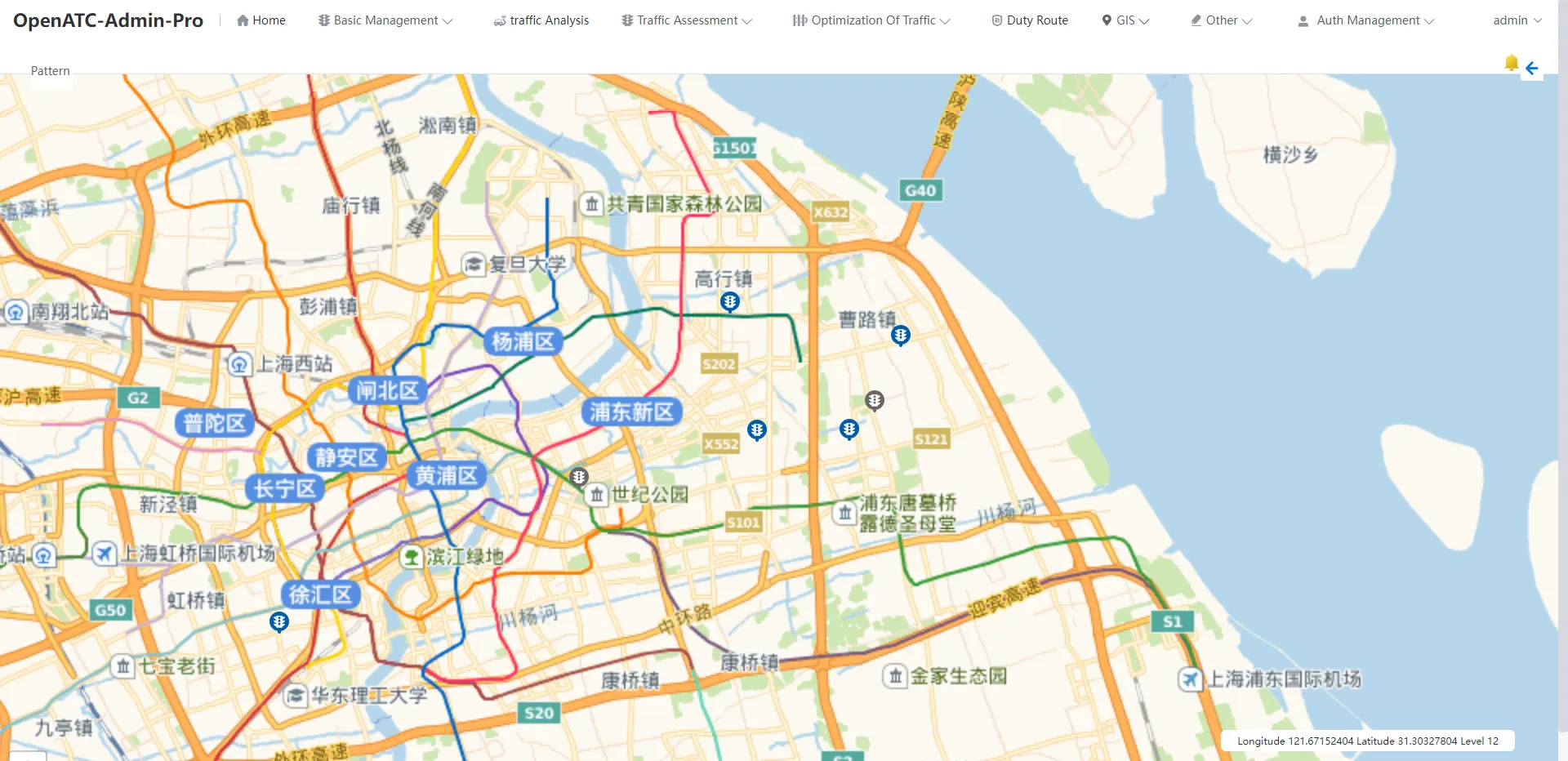
1) Click on the toolbar on the right side of the page button to hide the toolbar, as shown in the figure below:
2) Click on the toolbar on the right side of the page button to expand the toolbar.
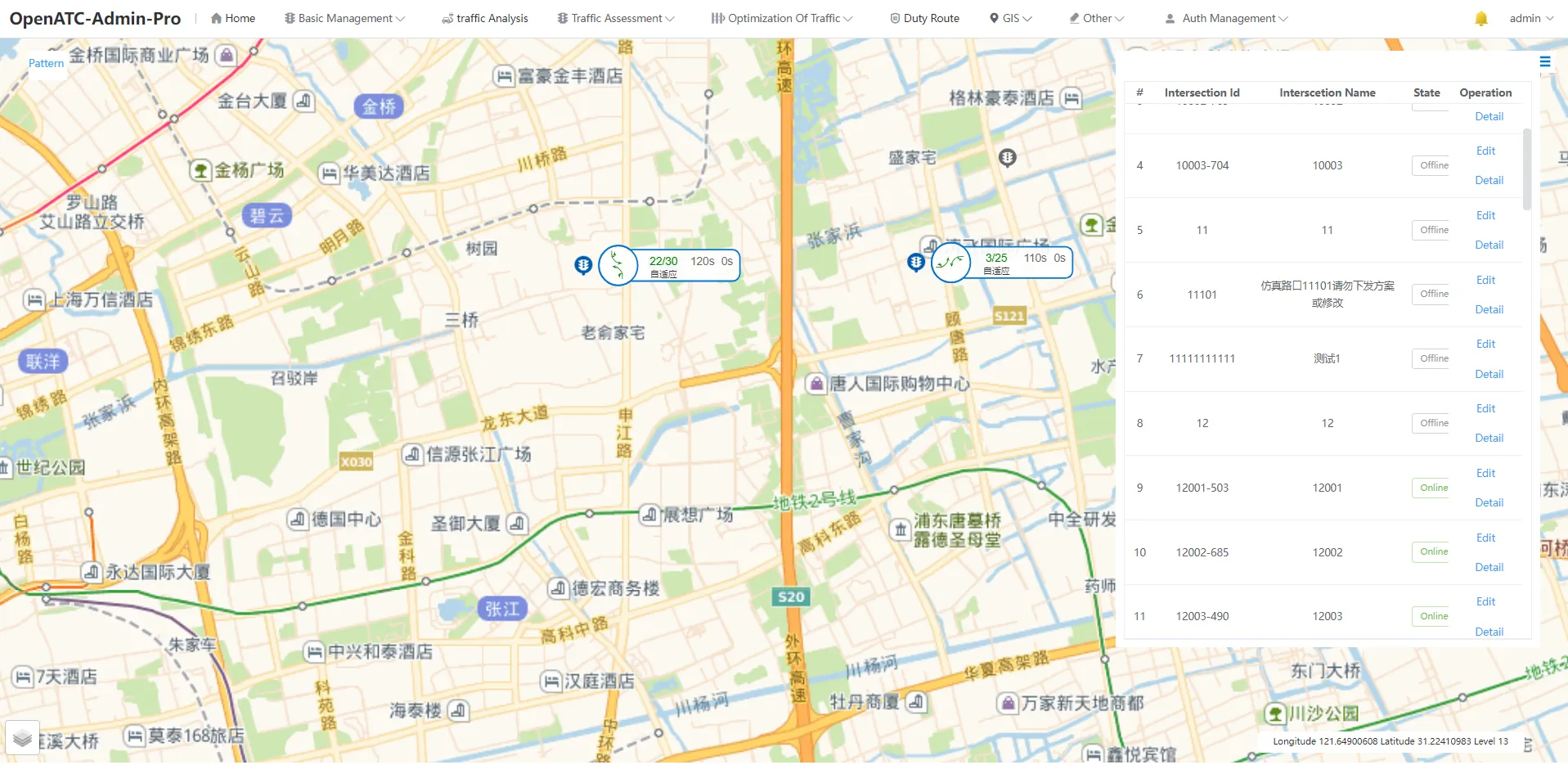
Click "Pattern" in the upper left corner, and the interface will display the scheme of the online device, including information such as current phase, green signal ratio, countdown, phase difference, period, and control mode.
3.2 Duty Route
Click "Duty Route" in the top menu bar and select any special service route to view the details corresponding to each device of the special service route, including: execution mode, duration, remaining time on duty and execution plan. Click "Execute Now" and the junction device performs a secret service mission.
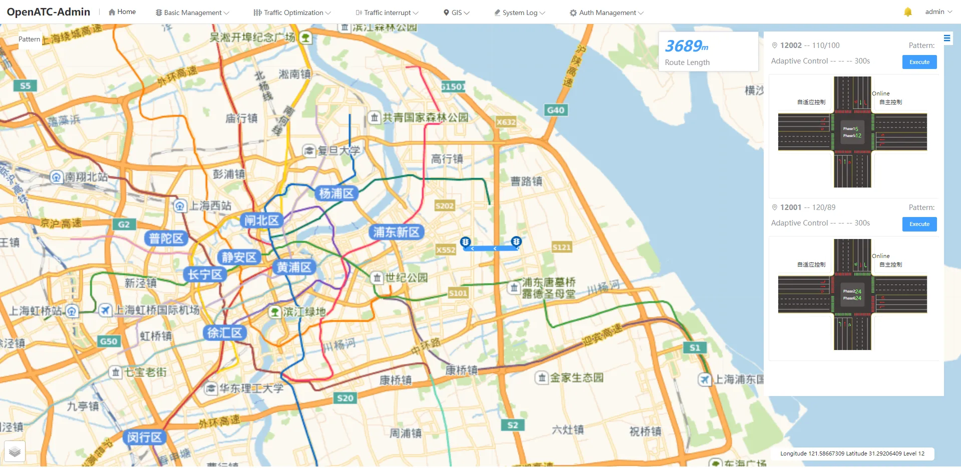
Toolbar:
1) Click on the toolbar on the right side of the pagebutton to hide the toolbar, as shown in the figure below:
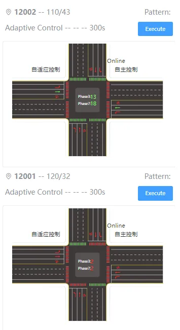
2) Click on the toolbar on the right side of the pagebutton to expand the toolbar.
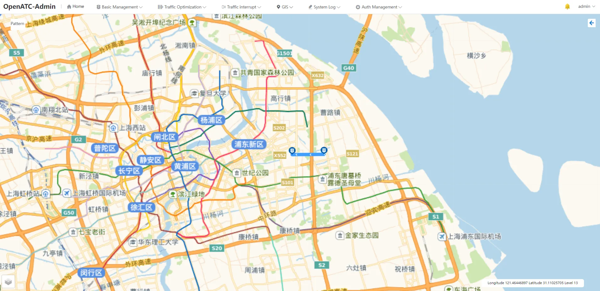
3) Click on the bottom right corner of the interface button to select "GIS" or "Image".
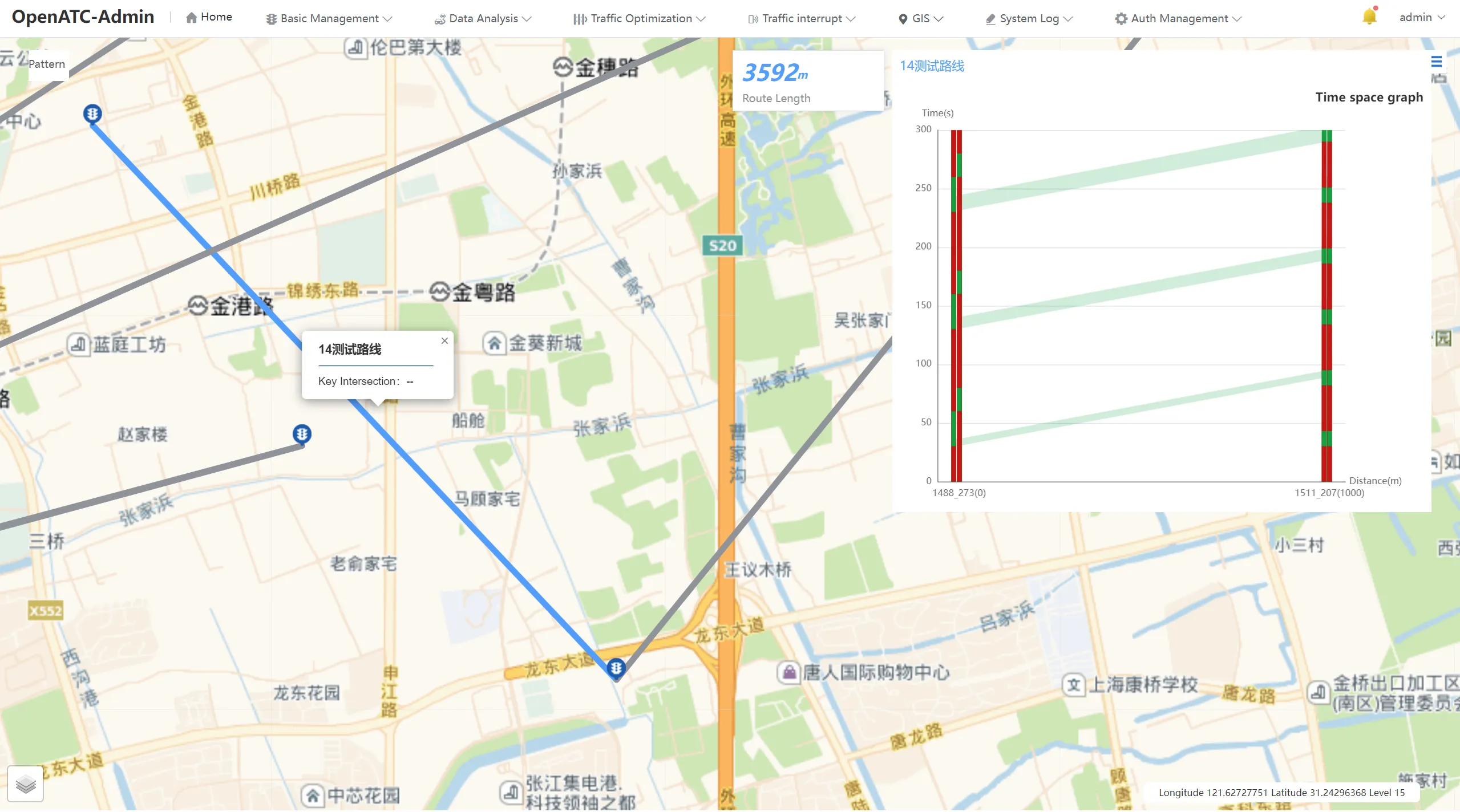
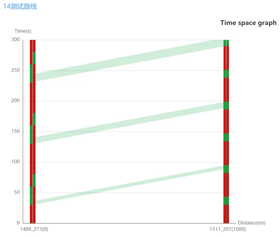
3.3 Coordinate Route
Click "Coordinate Route" on the top menu bar and select any coordinated route to view the real-time time-distance map corresponding to the coordinated route group.
Toolbar:
1) Click on the toolbar on the right side of the pagebutton to hide the toolbar, as shown in the figure below:
2) Click on the toolbar on the right side of the pagebutton to expand the toolbar.